
Test 7 - Camshaft and Crankshaft Synchronisation
The Camshaft and Crankshaft sensors provide valuable information about the engine. They are definitive in determining engine timing as they reflect the absolute mechanical position of the engine.
Use them as a reference when diagnosing ignition timing and VVT problems.
- Software: PicoScope 6 - Guided Test AT151
- Purpose of Test - Examine Crankshaft and Camshaft Sensor Signals
- Skill Level Required - Easy
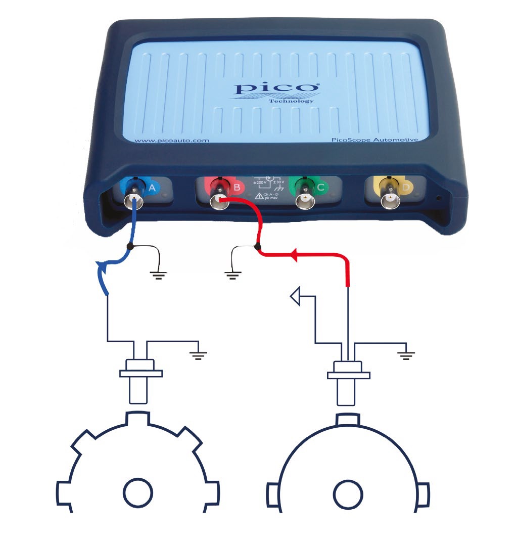
Connect: Locate the Camshaft and Crankshaft Sensors using your vehicle’s technical data. We recommend you use either back-pinning probes or breakout leads to make the connection. Use technical data to identify the signal wires. Don't forget to ground both channels.
Run: The engine must be idling to complete this test. Start PicoScope when you are ready to capture the signal.
Read: There should be a consistent pattern that develops as you capture data throughout 720° of crankshaft rotation. Cam and crank signals can provide invaluable timing reference data for waveform comparisons.
Remember to extend the timebase to allow you to see multiple revolutions together. If each 360° camshaft revolution is consistent, it is likely that the synchronization between the camshaft and the crankshaft is correct, and that both sensors are working correctly. Inconsistencies will highlight probable valve timing issues, sensor faults or short circuits within the associated wiring looms.
Waveform Analysis
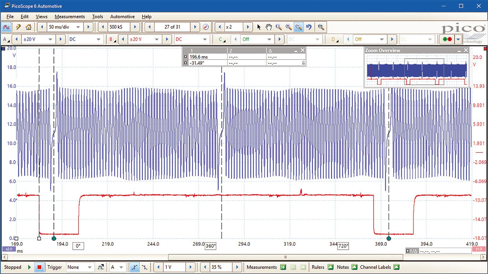
The Crankshaft signal in Channel A clearly shows the missing tooth used for synchronisation. It is an inductive sensor so the amplitude of the signal gives a rough indication of the speed of the engine during the cycle. If you look carefully, the amplitude changes showing the acceleration due to combustion and deceleration due to compression.
The Camshaft turns at half the speed of the crankshaft and one pulse is seen every 720 degrees - normal for a four-stroke engine. Note: some camshafts have multiple pulses but the pattern repeats every 720 deggrees.
Notice the rotational rulers (green dots) that you can apply to estimate the number of degrees that the engine has turned at any point in the cycle. The ruler set at the beginning of the first cam pulse is 31.49 degrees before the missing tooth on the crank.
CAM Crank Sensor Test Animation
Video Commentary
The videop starts by showing the two Camshaft Sensors and the Crankshaft Sensor sending signals to the ECU.>
Connect: Using backpinning probes, locate and connect to the signal wires of the Cam and Crank Sensors. Remember to ground both channels in use (the 4x25 and 4x25A channels float and all channels being used must be provided with a reference, ground in this case).
Run: Start the engine and allow it to idle whilst capturing the waveforms.
Read: Examine the waveforms and note the correlation between the Camshaft and Crankshaft.
Please click Next for the eighth test - MAF Snap WOT Throttle Test.