| Automotive Oscilloscope Comparative
Specifications
|
|
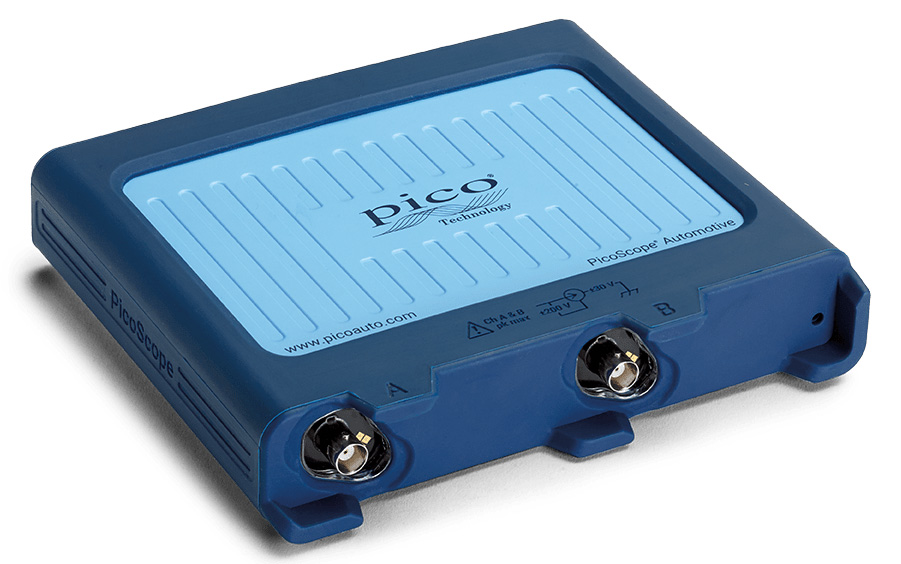
PicoScope 4225A
|
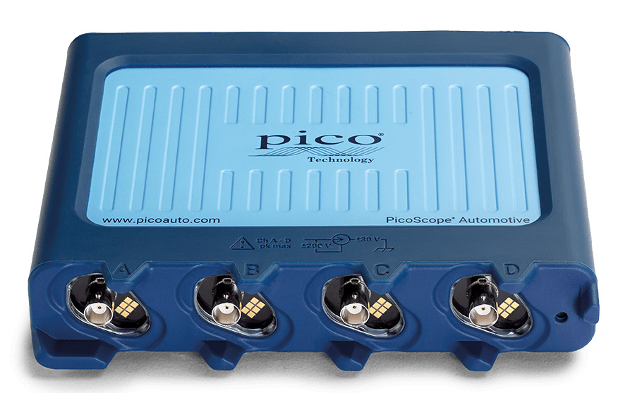
PicoScope 4425A
|
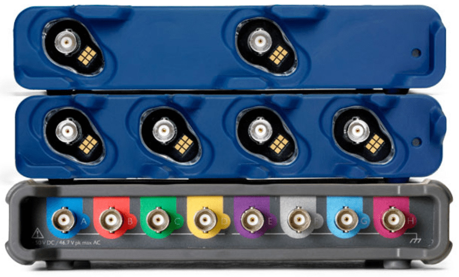
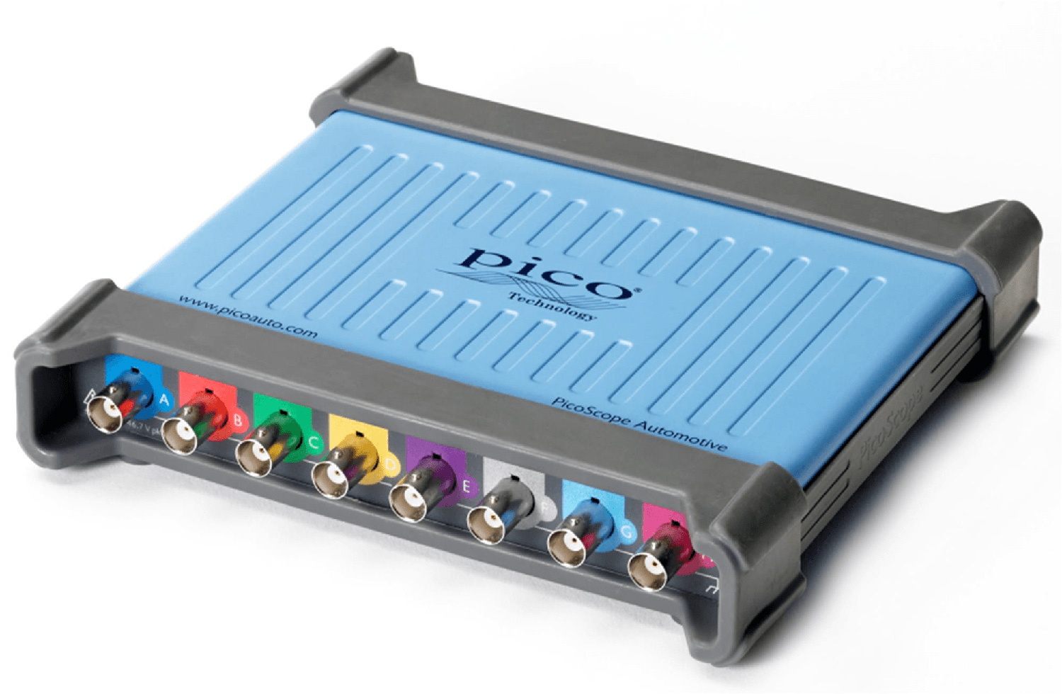
Picoscope 4823
|
|
Oscilloscope Vertical
|
Channels 
Channels are the number of inputs or the number of waveforms that can be shown
simultaneously.
|
2 |
4 |
8 |
Bandwidth
Bandwidth is the frequency an oscilloscope can display. High frequencies are the
signal's detail. As the signal frequency increases near the bandwidth limit, the scope cannot amplify the
signal and the wave gets smaller on the display. The bandwidth is usually specified as the frequency at
which the scope displays the signal at half of its true size. If you want to see all
the details in a signal accurately, there is a rule of thumb: the bandwidth needs to be five times the
frequency of the signal you are trying to see! Many competing automotive oscilloscopes only have a bandwidth
of between 200 kHz and 2 MHz, and therefore you can only see signals between 40 kHz and 400 kHz reliably,
compared to the PicoScope, which can see 4 MHz.
|
20MHz (10MHz on ±50mV Range) |
20MHz (10MHz on ±10mV and ±20mV Ranges) |
Vertical Resolution
The vertical resolution is the number of bits determine the number of discrete
values (dots) that can be displayed vertically on your graph. An 8-bit scope can only display 256 dots,
resulting in a grainy display. A 12-bit scope can display 4,096 dots, resulting in a far smoother display
and
greater accuracy. The extra 4-bits means that for every dot displayed by an 8-bit scope, a 12-bit scope
displays 16 dots.
|
12 bits (4,096 dots) |
Enhanced Resolution
If a repetitive signal is displayed, the scope's resolution can be enhanced even
further. An improvement of up to four bits can be achieved which can increase the resolution of a 12-bit
scope to 16 bits. That means that up to 65,536 discrete levels can be displayed yielding an ultra smooth
waveform.
|
16 bits (65,536 dots) |
DC Accuracy
This is the absolute accuracy of a displayed DC level. If you read 10 V then, if
the accuracy is ±1%, then the actual voltage could be any value from 9.9 V to 10.1 V.
|
±1% of full scale |
±1% of full scale ±300 μV |
Input Sensitivity
Sensitivity shows what range of signals the scope can display (at full
resolution). There are 10 vertical divisions, thus the scope can display signals of 10 times these values
(Note: the safe input voltage limit is ±200V). Where appropriate attenuators are used, this range can be
increased.
|
10mV / div to 40V / div |
2 mV/div to 10 V/div (10 vertical divisions) |
Input Ranges (full scale)
When you use the scope, you can set the vertical scaling in ranges. There is
also an auto range that can set the vertical scale for you. The software will warn you if your signal is
outside the range you have selected. Again, appropriate attenuators can extend these ranges, and you can
define different probes which translate the ranges' scale or unit to suit the quantity being measured (e.g.
amps instead of volts).
|
±50 mV to ±200 V in 12 ranges |
±10 mV to ±50 V full scale, in 12 ranges |
Input Impedance
Input impedance means input resistance. It is important when you are measuring
voltages where the source impedance is high. Some sensors have high resistance outputs, and a low impedance
input can produce an inaccurate measurement. Some scopes have 50 Ω inputs, and if a sensor with an output of
10 V and an impedance of 1 kΩ (1,000 Ω) was to be measured, the value read would be 0.476 V, hopelessly
inaccurate. The PicoScope with an impedance of 1 MΩ (1 million ohms) would measure 9.98 V, an error of only
2%. The input capacitance affects high-frequency measurements because the impedance of a capacitor decreases
as the frequency increases. It is therefore desirable to have a high input impedance and a low input
capacitance.
|
1 MΩ in parallel with 24 pF |
1 MΩ ∥ 19 pF |
Input Type
BNC means a special, bayonet connector used to handle high
frequencies.
Single ended means that only one input is provided per channel and
voltages are with reference to its ground.
Floating means that each input is separate
from the other inputs and the rest of the scope. Each floating input needs its ground to be connected, and
you can use each channel independently without worrying that the grounds are connected to different places
or voltages (up to 30 V between channels). Floating inputs also increase reliability because the inputs are
separated from the others and the PC. Floating inputs is an invaluable feature that sets the 4425A and
4225A PicoScopes apart from most other scopes.
|
Floating, single ended, BNC Connectors |
Common ground, single ended, BNC Connectors |
Input Coupling
Input coupling (AC or DC) means that an input can accept DC values or can reject
DC so that you can focus on the varying part of the signal. Sometimes a signal has a large DC offset with a
small AC signal 'on top'. By selecting AC, the DC offset is removed, and you can amplify the AC signal to
see it much more clearly.
|
Software-selectable AC/DC |
Input Overvoltage Protection
The 4823 is only protected to ±100V. DC voltages in excess of
±100V or AC voltages in excess of 70 V may damage the inputs. Always use attenuators when
testing inductive devices such as ignition coil primaries, injectors and solenoids.
The absolute maximum voltage that can be applied to an input of the 4425 and 4225 is 250 V! Although this is
higher than most other automotive scopes can accept, don't try to measure an AC signal, like 240 V mains.
The peak value is far higher than 240 V, actually 340 V, which will damage the scope. The absolute maximum
AC sine wave that the 4425 or 4225 scopes can withstand is only 175VAC (if there is no DC
offset). For safety, we recommend that you never apply more than 200 V (140 VAC) to any input.
|
±250 V (DC + AC peak) |
±100 V (DC + AC peak) |
Input Common Mode
This specification is the absolute maximum voltage that can be applied between
channel grounds. Channel grounds are not connected on the 4425A and the 4225A, which means that
they must always be connected when measuring. Unlike other scopes, they don't have to be connected to the
vehicle ground, which allows differential measurements. The voltage from ground to ground on any channel
relative to any other channel must not exceed 30V. The 4823 has common grounds, which means that all grounds
are electrically connected. TIP you can use the maths channel feature (i.e. A-B) to do differential
measurements, using two channels, to work around this problem.
|
±30 V |
Common Grounds |