Automotive PicoScope Software


Automotive Oscilloscope Kits containing a PicoScope
PicoScope Software
PicoScope Automotive is the powerful software package that turns your PC into a diagnostic oscilloscope when used with a PicoScope device. PicoScope has been designed to make it easy for you to diagnose vehicle faults. Packed with features such as automated measurements, reference waveforms and the ability to save and print waveforms, PicoScope Automotive is the ultimate tool for your diagnostic toolbox.
Also included is PicoDiagnostics software to quickly test batteries, alternators, starter motors, compression, cylinder balance, NVH and can even balance a Propshaft on the vehicle. Professional reports allow you to show your customer what you have checked and any problems you have found.
Visit PicoAuto to get your free copy of the software with a built-in 'demo device' so that you can experiment and see how it works. It runs on Windows 7, 8 or 10. You can explore the capability and see how PicoScope can benefit your business and customers.
Regular updates to our software include new features and new tests, and are free for the life of the product.
PicoScope Guided Tests
There are over 150 guided tests, ranging from simple injector tests through to more complex topics such as CAN bus testing, integrated into the software.
When you select a guided test all settings are configured for you, and an example waveform is loaded. Diagrams and photos then show you the leads and accessories you need, how to connect to the vehicle, and how to perform the test.
Once the test has been completed you will find guidance on understanding the waveform, how the component works, and typical faults/fixes.
As vehicle technology changes we continue to add more tests through the free software updates.
Waveform library
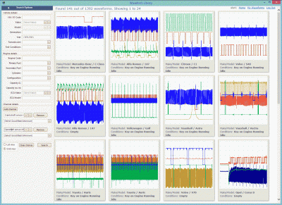
The library enables you to share and back up your waveforms online and also search a global database of waveforms uploaded by PicoScope users from around the world.
The powerful search options let you find “known good” waveforms from vehicles identical to the one you are working on. Not sure if you have a slipped timing belt? There are hundreds of cam vs crank waveforms to compare against.
Not sure if the cranking current is too high? Download a waveform to compare.
PicoScope Software - Continual Improvements
We have been upgrading and improving PicoScope software for over 20 years. This allows us to make the maximum use of the latest technology both in the oscilloscope hardware and the PC itself.
The modern user interface is uncluttered and easy to use. There are no old-fashioned knobs and dials. We leave most of the space free for what matters: your waveforms.
Recent new features include:
- 720 degree rotation rulers: ideal for looking at engine timing (see waveform showing crankshaft, camshaft and in cylinder pressure).
- Channel labels: it's important when saving a file to identify what each channel is measuring but it can be time-consuming. With channel labels you just type in a few letters and a time-saving list of names is presented.
- Vehicle database: a list of makes and models is included with the ability to store customer details too. The last few vehicles worked on are stored in a list for quick recall.
PicoDiagnostics
Alongside our PicoScope 6 software, you also have our highly powerful PicoDiagnostics software. Included free of charge, this software turns your PicoScope into a highly powerful diagnostic device. See the tests listed below for a glimpse into how PicoDiagnostics can turbocharge your performance.
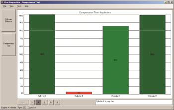
Compression Test
Check for mechanical issues in seconds: Simply clip the test leads to the battery and crank the engine. The relative compression of each cylinder is shown in an easy-to-understand bar graph format.
To show absolute compression, add an optional pressure transducer to one cylinder, and the software will calculate the pressure for all cylinders in bar or PSI.
Battery, Starter and Alternator Test
Did you know that your PicoScope also can operate as a highly accurate and efficient battery and charging circuit tester? This allows you to test your customers' vehicles without the need for dedicated, expensive test tools.
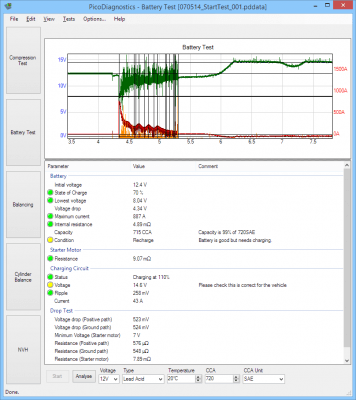
Using PicoDiagnostics, you can check the battery, starter, alternator, and wiring, all in one quick test. Easy-to-understand reports with red, amber or green indicators can be printed for customers, either to show the electrical system is in good condition, or to explain why a component needs replacing.
The battery test checks the state of charge, the voltage drop during starting, and compares the cold cranking amps (CCA) with the rating for the battery.
The charging test checks the alternator is correctly charging the battery and spots problems, such as overcharging or excessive ripple due to a blown diode.
The starter test helps identify a failing starter motor by measuring its coil resistance.
The drop test measures the voltage drop (and resistance) of the cables running from the battery to the starter motor. This will discover starting issues caused by corroded or damaged battery cables, or poor connections to the chassis ground.
Once your test is completed, you can print out a copy of the report for your customer. This report is fully customizable with your own company details and logo to give a professional appearance.
Cylinder balance / Misfire detect
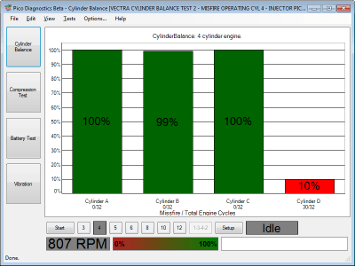
Check for misfires, and check if each cylinder is contributing the same amount of power, with the cylinder balance test.
Simply connect channel A of the PicoScope to the vehicle battery and start the engine. The software detects changes in engine speed as each cylinder fires. An easy-to-understand bar graph display shows the relative power output from each cylinder.
Please note: this test will not work correctly on certain vehicles that disable cylinders for emissions control reasons, or on low-compression engines with 8 or more cylinders.
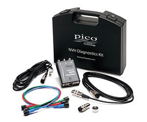
Noise Vibration and Harshness (NVH)
The PicoDiagnostics NVH software can analyze vibrations and help to diagnose NVH problems. All you need is a PicoScope Automotive oscilloscope, the PicoDiagnostics NVH kit and a software license key (available from Pico Technology support).
PicoDiagnostics has had strong development focus this year, ensuring the software performs and evaluates better than ever before. Special focus has been given to NVH testing and, in particular, the way to view results and additional vehicle data.

The main updates are:
- The new filter tab in the Advanced Options dialog box contains these options:
- Low pass filter – which allows any frequency below the set threshold to be detected.
- High pass filter – which allows any frequency above the set threshold to be detected.
- Band pass filter – which allows frequencies between the Low pass and High pass range to be detected.
- Band stop filter – which allows frequencies outside of the Low pass and High pass range to be detected.
- There is an added OBD PID functionality for managing and using Parameter IDs (PIDs). PIDs are codes that are used to request data from a vehicle for diagnostics. The SAE standard J/1979 defines several PIDs, but many more PIDs are specified by the respective vehicle manufacturer. Typically, technicians use PIDs with a scan tool connected to the vehicle's OBD-II connector. The PID is sent to the vehicle's controller area network, a device on the bus recognizes the PID and reports the value for it back to the bus, from which it is sent to the scan tool and displayed to the technician. Note: You can only view the values from the PIDs in the Time Domain view on the record and analyze tab.
- Time domain is a real-time feature you can use to measure harshness, such as knocks, creaks and squeaks. Noises and harshness like these are annoying but are only present for a very short period of time, with insufficient energy to be transferred to and displayed in the Frequency display (FFT) of the NVH user interface. Events (e.g. pothole strikes) are not transferred for display in the FFT as it requires a minimum of 2.5 seconds of continual disturbance in order to process the event. Until now, symptoms like these would be reserved for listening devices, letting the technician listen to the intensity of noises delivered to a headset from microphones placed around the offending area of the vehicle. These results, however, would be subjective and open to misinterpretation. These events are captured in the signal history as it displays the input of the attached microphone or accelerometer live (relative to time). The time domain feature will capture and display the momentary amplitude of these noises.
