
Introduction to PicoScope Automotive Diagnostics
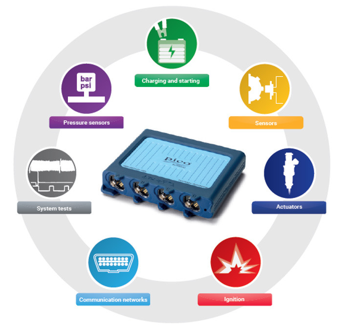
PicoScope is a powerful automotive diagnostic system based on an oscilloscope that gives you detailed insights into your vehicle’s electrical; electronic; mechanical; pressure-related; and noise, vibration, and harshness (NVH) systems. It is supplied as a stand-alone instrument with a USB cable, or in a number of kits equipped with many accessories that you use to connect to and test the systems of your vehicle.
It is user-friendly, with advanced features like waveform comparison, easy data sharing, and non-invasive testing. This ensures that you can diagnose issues accurately and efficiently. Whether you are a seasoned technician or just starting out, PicoScope helps you get to the root of problems faster and more reliably than ever before. Pico can be used on any vehicle, including Petrol, Diesel, Electric Vehicles (EVs), Heavy Vehicles, and Earth-moving Vehicles. Thousands of tests can be performed.


| R 19,307.00 ex VAT | R 2,896.05 VAT | R 22,203.05 inc VAT |

| R 30,885.00 ex VAT | R 4,632.75 VAT | R 35,517.75 inc VAT |

| R 55,066.00 ex VAT | R 8,259.90 VAT | R 63,325.90 inc VAT |
TRAINING
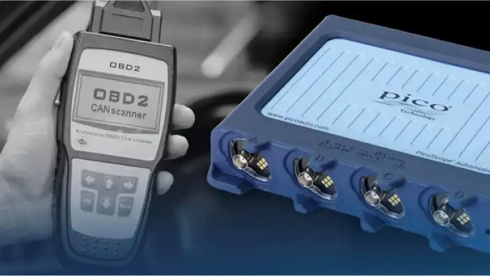
Download PDFI have a Scan Tool, why do I need a PicoScope?
A PicoScope is not, and does not replace, your scanner or OBD tool. It works with it to help you find and diagnose the real cause of a problem.
There are many Scan Tools available. All rely on the vehicle's ECUs (Electronic Control Units) to produce fault codes that show the general location of a problem.
What if the ECU or CAN bus is faulty, can you rely on a fault code? What if the fault code can be as a result of many different problems? What if there is no fault code?
Do you swap components until the problem goes away? This can be costly, especially where components might code themselves to the vehicle when they are installed.
Typically:
- You would start with a Scan Tool to find the location of the fault (fault codes).
- Then you would use your PicoScope to test the components and trace the real cause of the problem.
- Once you have proved the fault, you would repair or replace the component that you have verified is faulty.
- To confirm that the repair is effective, you would retest using your PicoScope to ensure that the cause of the problem has been eliminated;
- Then you would use your Scan Tool to clear the fault code; and
- Finally, use your Scan Tool to check that the fault code does not recur.
Also, remember that PicoScope does a lot more than simple fault diagnosis. It can be used to measure pressure, diagnose Noise, Vibration, and Harshness (NVH) problems, take measurements, and much more, as will be discussed below and in subsequent pages.
I use a Multi-Meter, why do I need a PicoScope?
A multi-meter can measure static values such as the battery voltage, current through a lamp, resistance of a coil, and continuity. However, in addition to its ability to measure static values, a PicoScope can show how things change. It can also measure things that happen very quickly, such as spikes, ignition pulses, communications, etc.
The new Automotive PicoScopes have a bandwidth of 20 MHz (20 million cycles per second) and a sampling rate of up to four hundred million samples per second. Two hundred and fifty million samples of 4,096 levels can be accommodated in its buffer. A multi-meter has many applications, but its tiny storage space and limited sample rate, 2 to 10 samples per second, cannot replace the functionality of and insight provided by a PicoScope.
The PicoScope has enormous storage capability and can also be used to look at things that happen very slowly. Find that elusive, intermittent fault by looking back through the PicoScope's waveform buffer or by creating a long capture, which you can zoom into, of over 13 hours with 5,000 samples per second over that period.
Getting Started
For new users, our Automotive PicoScopes stand out due to their user-friendly design and supportive features that make complex diagnostics accessible to all.
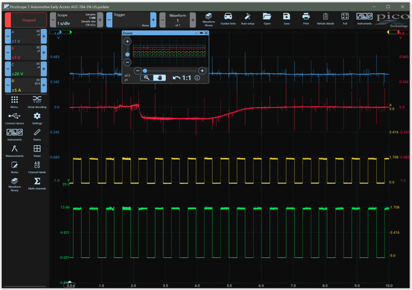
User-friendly software that doesn't overwhelm
Automotive PicoScopes feature an intuitive, easy-to-navigate software interface that helps you to understand and to start diagnosing quickly, with powerful features. The software has clear menus and icons and is logically laid out to guide you through the process of setting up and conducting measurements without overwhelming you with technical complexity.
PicoScope software is free, and there are no subscriptions. There are two versions, Stable for production work and Early Access to allow you to try out new features. The software is updated regularly, and the new features upgrade and improve your PicoScope continually.
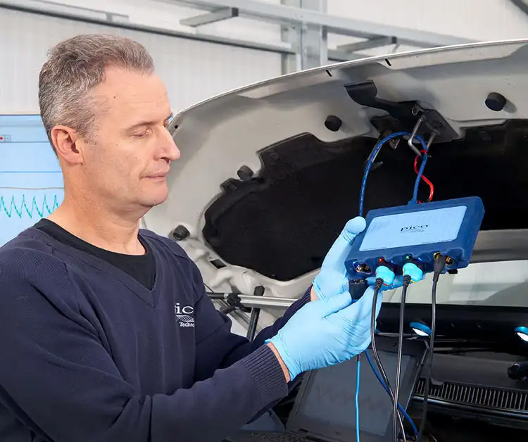
PicoBNC+ makes setup easy
PicoBNC+ is a smart probe interface that identifies the accessory you plug in, configures your PicoScope and your probes automatically, ensuring that you always have the correct settings. The interface provides power to accessories ensuring that your probes are always on (no batteries are required!) and ready for immediate use. In addition, the interface's channel status light provides clear indicators of probe connection and status.
The PicoBNC+ inputs on your 4x25A PicoScope are backward compatible with the old BNC accessories, allowing you to continue to use your older accessories with your new PicoScope.
Support with our Guided Tests
PicoScope Automotive software comes with a range of pre-configured Guided Tests, tailored for common automotive diagnostic tasks such as testing ignition systems, sensors, and injectors. By selecting a Guided Test, you can start diagnostic procedures without needing to manually configure your PicoScope, significantly reducing the learning curve. Experts also use Guided Tests to avoid having to set up the scope, saving both time and money.
In addition to the comprehensive test guides which include, connections, steps, and even applicable fault codes, the Guided Tests provide in-depth system, component, and waveform explanations and support. Guided Tests provide you with everything you need to help you identify whether you have found a fault.