
Oscilloscope Probes
An oscilloscope probe is the original oscilloscope accessory. Scope Probes are used to connect the scope inputs to the system being tested. The PICO-TA375 is a conventional 1:1 10:1 switchable probe with a BNC connector. The new PicoBNC+ 10:1 probe PICO-TA506 is ideal for automotive use as it has PicoBNC+ and is able to probe high voltages and high-speed signals. The PICO-PQ345 differential probe, also PicoBNC+, is used for very high voltages, up to 1.4 kV and is ideal for EV testing and where you need to measure signals that are not referenced to ground.
Pico also supplies a range of Premium Test Leads in 3 m and 5 m. These are 1:1 and are suitable for general purpose testing. See the Premium Test Lead page for more details.
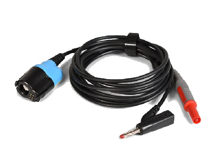
PICO-TA506 PicoBNC+™ 10:1 Scope Probe and Adaptor
The PICO-TA506 PicoBNC+™ 10:1 Scope Probe and Adaptor has fixed 10:1 attenuation and is intended for both high-speed signals like CAN and FlexRay and for higher voltage signals, such as primary ignition. It is the equivalent of the existing PICO-TA375 Oscilloscope Probe switched to 10:1 and the old PICO-TA499, which it replaces.


| R 569.00 ex VAT | R 85.35 VAT | R 654.35 inc VAT |

| R 1,614.00 ex VAT | R 242.10 VAT | R 1,856.10 inc VAT |
Watch — Attenuators: Then and Now

| R 9,710.00 ex VAT | R 1,456.50 VAT | R 11,166.50 inc VAT |
Watch — 1,400 V Differential Oscilloscope Probe
The above animation shows the old PICO-TA499. The new PICO-TA506 connects in the same way. The PICO-TA506 has the advantage of flexible leads at the 4 mm plug ends, just like a standard test lead. The probe works with the latest 2 and 4-Channel 4X25A PicoScopes and thanks to PicoBNC+, it is automatically recognised and set up by the PicoScope 7 software when connected.
Using 10:1 Probes and Attenuators for High Voltage Measurement — Do!
10:1 probes such as the PICO-TA506, the old PICO-TA499 and PICO-TA375 Scope Probe (set to 10:1 only, 1:1 mode cannot handle high voltages) and the 10:1 or the old 20:1 Attenuators can be used to measure high voltages such as primary ignition.
Primary ignition (the voltage on the primary of an ignition coil) can easily exceed 400 V. The 4x25 and 4x25A PicoScope inputs may not exceed 250 V. The 8-channel BNC 4823 and older BNC automotive PicoScopes have lower voltage maximum limits (e.g. 100 V). Measuring high voltages without any form of attenuation (e.g. using 1:1 Test Leads) is dangerous and can damage your PicoScope.
Always use attenuation when measuring high voltages.
Using a 1:1 Test Lead for High-Speed Measurements — Don't!
A 1:1 Test Lead should not be used for high-speed measurements. Adding a 10:1 Attenuator such as the PICO-TA197 and the older 20:1 Attenuators makes the situation worse.
If we consider CAN, CAN-FD and FlexRay as high-speed examples, the reasons become clear:
- Remember that an attenuator is installed on the scope end of a 1:1 Test Lead. The use of a Test Lead means that the network has a stub (a branch) of 3 m or 5 m depending on the Test Lead being used. This causes reflections and can distort the signals on the network. Distortion leads to false measurements and, in some cases, can cause the network to fail.
- The maximum stub length on a CAN network is specified as 300 mm, not 3 m or 5 m.
- Test Leads have capacitance which loads the network and can also cause message transfer to fail.
Incorrect measurement techniques can cause incorrect, distorted waveforms and even cause the network to fail. Use 1:1 Test Leads for low-voltage, low-speed measurements. Add an attenuator for high voltages but do not use 1:1 Test Leads (with or without an attenuator) for high-speed signals.
Using 10:1 Probes for High Speed Measurement — Do!
The PICO-TA506 (and the old version - PICO-TA499) and the PICO-TA375 (set to 10:1 only) can all be used to measure high-speed signals. They apply minimal capacitive loading and isolate the length of the lead from the network.
The input impedance of a PicoScope is 1 MΩ. A 10:1 probe adds a 9 MΩ resistor at the probe-end of the lead. This resistor isolates the probe's lead from the network and minimises capacitive loading. There is no stub and very little capacitance. Your measurement is accurate, and the network is (almost) unaffected by the probe.
Recommendations
Always use 10:1 probes such as the PICO-TA506 and the old version - PICO-TA499 for all measurements except where long leads are required and where very low voltages need to be measured. Using 10:1 probes is safer (dangerous high voltages are reduced) and provides more accurate measurements as the probe can measure higher frequencies and does not affect the circuit being measured.
As high-speed networks such as CAN have two signal wires, you need two probes to measure both signals. The standard kits and the Garage Lube diagnostic kits only have one PICO-TA506, so you might consider adding another probe to your kit.
PICO-TA375 100MHz Oscilloscope Probe
These 100 MHz high-quality, general purpose oscilloscope probes have enough bandwidth to examine high-speed signals such as the control and communication buses in modern vehicles. A two-position slide switch allows attenuation of either x1 or x10 to be selected.
They are supplied with a range of accessories such as a clip used to attach the probe to the wire you are probing, a ground clip, a screwdriver used to adjust probe compensation and coloured identifiers.
This probe is particularly useful if you want to probe CAN bus and FlexRay signals.
Documentation
PICO-TA375 100MHz Scope Probe User's Guide
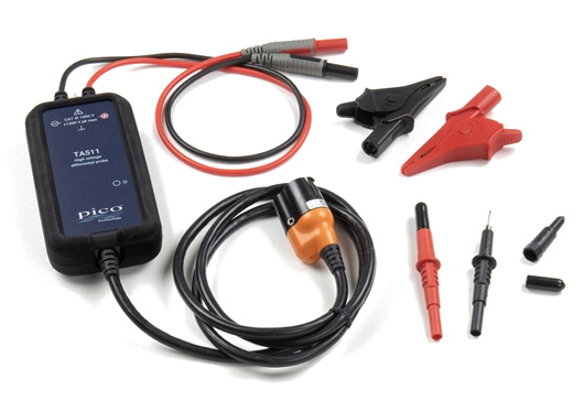
PICO-PQ345 Differential Oscilloscope Probe x20/x200
The PICO-PQ345 PicoBNC+ Active Differential Oscilloscope Probe lets you use a standard earthed oscilloscope to measure signals that are not referenced to ground. Use these probed for very high-voltage applications such as EV Testing and where you need to measure signals that are not referenced to ground.
As the name implies, the PicoScope sees the difference in voltage between the two input test leads.
| Quantity | SKU | Description |
|---|---|---|
| 1 | PICO-DO378 | Safety Guide: TA511 High Voltage Differential Probe |
| 1 | PICO-TA005 | Dolphin clip 1,000 V CAT-III (black) |
| 1 | PICO-TA006 | Dolphin clip 1,000 V CAT-III (red) |
| 1 | PICO-TA310 | Multimeter style prod 1,000 V CAT-III (black) |
| 1 | PICO-TA311 | Multimeter style prod 1,000 V CAT-III (red) |
| 1 | PICO-TA511 | PicoBNC+ 1,400 V Differential Probe |