
Single Line Centralised Lubrication System Injectors

A Single Line Centralised Lubrication System has a pump that feeds a single line (pipe) connecting multiple injectors together. When the pump is running, all of the injectors dispense a metered quantity of lubricant simultaneously. Once all injectors have dispensed, the flow ceases and the line pressure rises sharply. A pressure sensor near the end of the line detects this pressure rise, the pump cycle ends and the line vents, causing the pressure to drop. As the pressure drops, lubricant inside the injector automatically recirculates and refills the measuring chamber ready for the next cycle.
Advantages
- Lubricated components last longer
- Boundary friction and wear is reduced by regular lubrication
- Precise lubricant dosing yields reduced lubricant consumption and cost
- System is extendable without redesign
- Works in demanding environments
- Simple operation
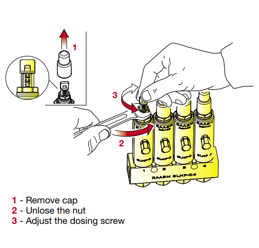
- Each injector's delivery quantity is easily adjusted
- Lubrication continues even if an injector blocks
- Visual injector operation indicator
- Pump oil or grease safely
Download the Single Line Lubrication Catalogue.
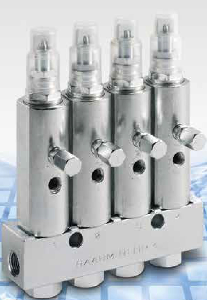
Injectors
The SLHP-D Single Line Volumetric Injectors are made from white-galvanised steel and are fitted with Viton seals. An adjusting screw is used to set the quantity of lubricant that will be delivered per cycle. A visual indicator allows the user to verify correct operation. These injectors conform to the dimensions of competing injectors allowing easy replacement. The design of the system allows for expansion and facilitates easy maintenance.
| Manufacturer | Raasm |
| Injector Flow Rate | Adjustable from 0 to 1.7cm3/cycle |
| Working Pressure Oil | 40 - 150 bar |
| Working Pressure Grease | 40 - 300 bar |
| Lubricant Inlet Connection | F 3/8" NPTF |
| Lubricant Outlet Connection | F 1/8" NPTF |
| Material | Galvanised Steel |
| Suitable Lubricants | Oil > 40 cSt or Grease max NLGI 2 |
Injector Schematic
The line (pipe) entering from the top left is the feed from the pump. The line passes from manifold to manifold. The injectors are attached to the manifolds and are supplied with lubricant from below. The first manifold in this system has eight injectors. Each injector's output is routed to a lubrication point and each injector can be adjusted so that each lubrication point receives exactly the right amount of lubricant.
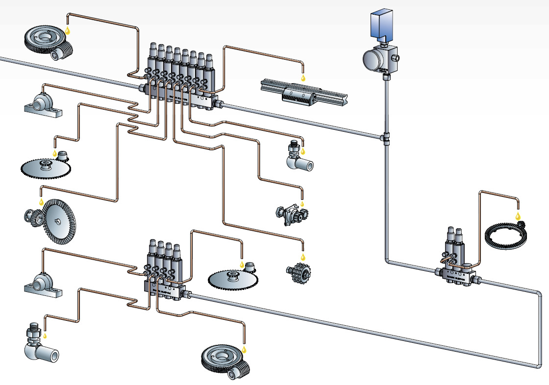
The line is then routed to the next 2-way manifold where the output flow of both injectors has been combined to increase the flow to the gear assembly.
The line continues to the final four-way manifold where four more lubrication points are supplied with lubricant. The outlet port of the last manifold is blocked.
In this example, a pressure switch has been included between the first and the second manifold. When the pressure switch detects high pressure, the pumping cycle ends. Usually, the pressure switch is installed at the end of the line or just before the final manifold. This allows the system to detect any blockages over the entire length of the line.
SLHP-D Grease Injector Components and Operation
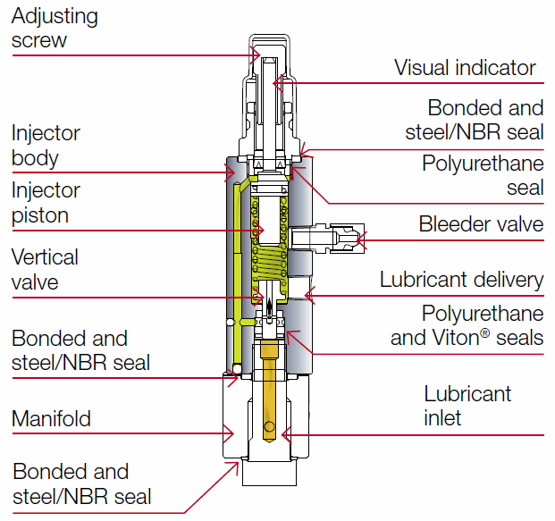
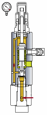
Idle - Between Cycles
The injectors are mounted on the manifolds and are supplied with lubricant from below through the lubricant inlet.
In between cycles (idle), the line is depressurised having been vented. The injector pistons are up and vertical valves are down inside all of the injectors having been forced apart by the spring.
The adjusting screw limits the upward travel of the injector piston thereby determining the quantity of lubricant that can be dispensed.
The visual indicator moves with the piston: down when lubricant is being forced out of the injector (dispensing); and up when the system is vented and the dispense cavity below the piston is being recharged.
Pressurisation and Delivery
When a cycle starts, the vent valve is closed and the pump runs. System pressure starts to rise in the line.
That pressure forces the vertical valve in the injector to move upwards, compressing the spring, until it collides with the piston. The movement opens the port to the left which allows lubricant (orange) to be pumped into the space above the injector piston (small red arrow).
The piston is forced downwards (grey arrow) by the lubricant being pumped into the space above it and the lubricant below the piston (green) is forced out, delivered under pressure, as the piston moves downwards.

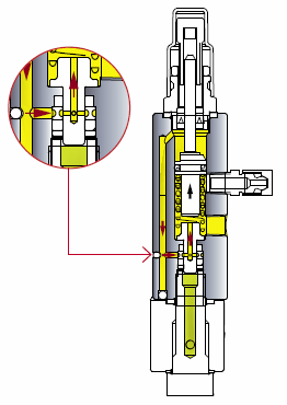
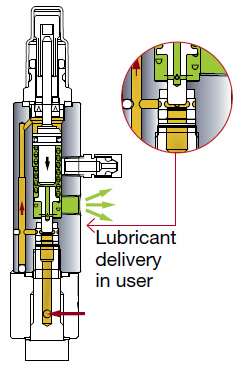
Flow complete - Pressurising
Left Image: When the piston has reached the limit of its downward movement, no more lubricant can flow into the injector. When all of the injectors reach this state, all flow ceases and the pressure rises sharply in the line.
The end-of-line pressure switch activates and pumping stops. The vent valve opens which releases pressure in the line.
Venting - Internal Recirculation
Right Image: When the pressure releases, the spring can expand. The piston moves up and the valve moves down. The space below the piston fills with lubricant drawn from above the piston. The quantity is limited by the piston's upward travel which is set by the adjusting screw.
The system has returned to the idle state, see above, and is ready to start a new pump cycle.
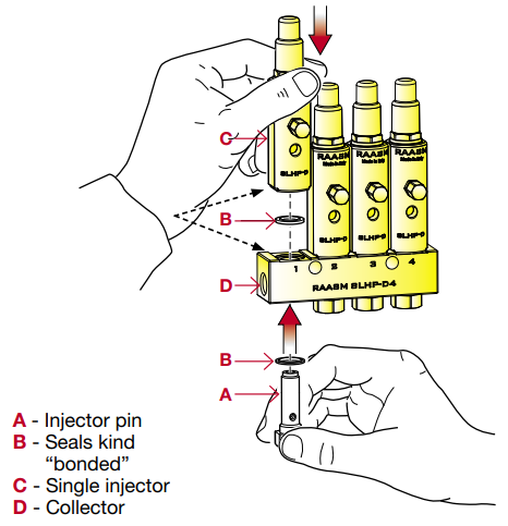
Installing an injector onto a Manifold and Adjusting Flow
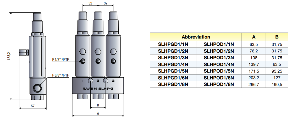
Dimensions
Ordering Information
| Grease (70-300 bar) | Oil (40-150 bar) | ||||
|---|---|---|---|---|---|
| Description | SKU | Abbreviation | SKU | Abbreviation | Outlets |
| Single Injector | 1532541 | - | 1538421 | - | 1 |
| Injector/s + Manifold | 1532540 | SLHPGD1/1N | 1538420 | SLHPOD1/1N | 1 |
| 1532580 | SLHPGD1/2N | 1538460 | SLHPOD1/2N | 2 | |
| 1532620 | SLHPGD1/3N | 1538500 | SLHPOD1/3N | 3 | |
| 1532660 | SLHPGD1/4N | 1538540 | SLHPOD1/4N | 4 | |
| 1532700 | SLHPGD1/5N | 1538580 | SLHPOD1/5N | 5 | |
| 1532740 | SLHPGD1/6N | 1538620 | SLHPOD1/6N | 6 | |
| 1532780 | SLHPGD1/8N | 1538660 | SLHPOD1/8N | 8 | |