
Electronic Throttle Control (Drive By Wire)
Introduction
The throttle cable has almost become redundant on today’s motor vehicle. The drive-by-wire system is by no means a new concept as it was introduced by BMW on their 7 series range back in 1988. The system BMW use is referred to as EML (German term for electronic throttle control). The system has now found its way onto other vehicles with humbler routes and can be found on base models. Historically a mechanical linkage between the accelerator pedal and the throttle butterfly has always existed, be it via a cable or via rods and linkages. These have now been replaced by sophisticated electronic control modules, sensors and actuators. This system is also referred to ‘Fly-by-Wire’.
There are several reasons why electronic throttle actuation is preferable to a conventional throttle cable:
- The vehicle’s on-board electronic systems are able to control all of the engine’s operation with the exception of the amount of incoming air;
- The use of throttle actuation ensures that the engine only receives the correct amount of throttle opening for any give situation;
- The optimisation of the air supply will also ensure that harmful exhaust emissions are kept to an absolute minimum and driveability is maintained, regardless of the circumstances. Coupling the electronic throttle actuation to the adaptive cruise control, traction control, idle speed control and vehicle stability control systems also means finer control can be achieved.
The use of such a system has advantages over the conventional cable version by:
- Eliminating the mechanical element of a throttle cable and substituting it with fast responding electronics reduces the number of moving parts (and associated wear) and therefore requires minimum adjustment and maintenance;
- Greater accuracy of data improves the driveability of the vehicle, which in turn provides better response and economy.
Variations
The first versions of electronic throttle actuation or EML were based upon the option of becoming a production line ‘add on’ system. It utilised its own Electronic Control Module (ECM), without the requisition of additional hard wear (and programming) to the vehicle’s original ECM.
This was achieved by inputting minimal data into the vehicle’s ECM via a serial link from the electronic throttle actuator’s separate control unit, as illustrated above.
Today’s systems have a specific ECM that incorporates the necessary programming to facilitate the input signals from the throttle pedal potentiometers and signal outputs to the electronic throttle body, as shown to the right.
Pedal Assembly
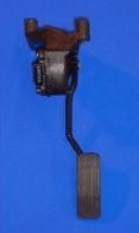
The throttle pedal has two potentiometers attached to it, achieving the accuracy required from the pedal’s movement. The photograph on the right shows the throttle pedal assembly with the potentiometers attached to the side.
The resistance ‘felt’ when the pedal is depressed is designed to give the same feel as a conventional throttle. The throttle pedal, in this instance, has 6 electrical connections.
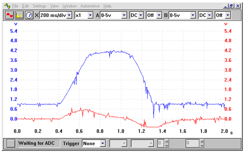
The PicoScope Automotive waveform shown in the example trace below shows the throttle moving from idle to WOT (Wide Open Throttle) and back once again to idle. In the example, the blue trace shows a conventional increasing voltage as the pedal is depressed, while the red trace operates over a lower voltage. Combined signals allow the ECM to calculate a mean voltage output from the two signals. This allows the pedal position to be calculated with greater accuracy than when only a single voltage output is taken into consideration.
Throttle Body
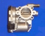
The absence of any mechanical linkage between the throttle pedal and the throttle body necessitates the use of an electric actuator motor.
The number of electrical connections may differ between different systems, while the example shown here has 6 electrical connections. These are to actuate the control motor and for the throttle position sensor.
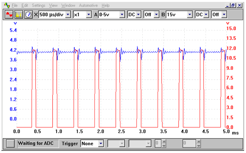
The actuator, often referred to as a ‘servomotor’ is operated by DC (Direct Current). The voltage received by the servomotor is in the form of a squarewave who’s voltage and frequency remain the same. The servomotor responds to the change in ‘duty cycle’.
The duty cycle is a percentage reading between the ‘on and off’ time. This change can be monitored on an oscilloscope.
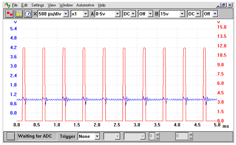
The waveform seen in the above illustration shows the duty cycle of the servomotor (in red) while the blue trace represents the position of the TPS (Throttle Position Sensor). As the load is increased, the duty cycle changes and further indexes the servomotor. This can be seen below:
Position Sensor
Integral to the servomotor (in this particular instance) is the TPS (Throttle Position Sensor). The voltage output from this particular sensor has to report back to the ECM the exact position of the throttle butterfly. With this in mind, the TPS in the same manner as the throttle pedal position sensor has two voltage outputs. These can be seen below:
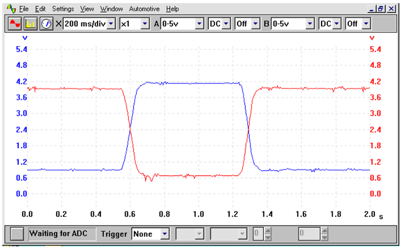
The waveform shown in the example trace shows the throttle moving from idle to WOT (Wide Open Throttle) and back once again to idle. The blue trace shows a conventional rising voltage as the throttle butterfly is opened, while the red trace is inverted. The combined signals allow the ECM to calculate a mean voltage output from the two signals allowing the throttle butterfly position to be calculated with greater accuracy.