
Test 4 - Injector Current and Voltage
An injector's current and / or voltage can be tested very easily. All that is required is a current clamp and a test lead with a backpinning probe.
- Software: PicoScope 6 - Guided Test AT004
- Purpose of Test - Suspected Compression Issues
- Skill Level Required - Very Easy
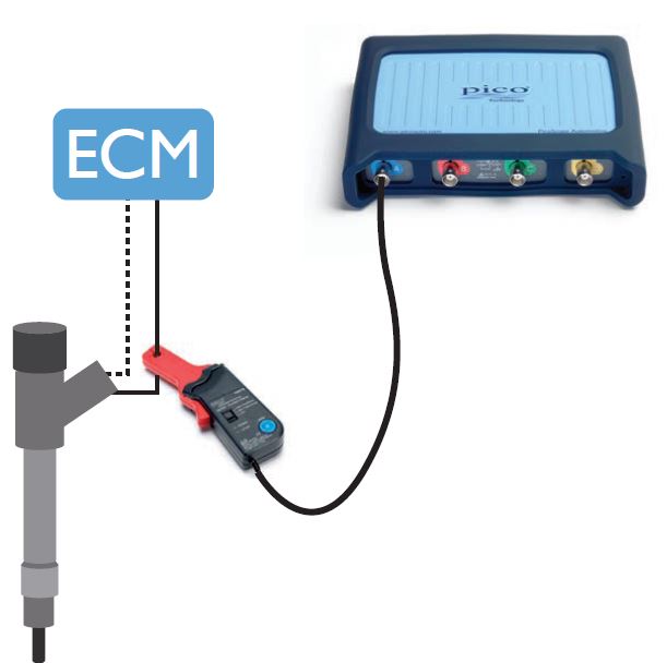
Connect: To test Injector Current, connect a PICO-TA018 20 A / 60 A Current Clamp or the new PICO-TA473 PicoBNC+ Current Clamp to Channel A on your PicoScope and place the clamp around the fuel injector supply wire. Note the orientation on the clamp. It may be necessary to pull back some of the loom’s outer shielding to fit the current clamp.
You can also monitor the injector voltage by connecting directly to the injector using another channel. As injectors can produce back EMF voltage spikes, we advise using a PICO-TA197 Attenuator or the new PICO-TA499 10:1 Scope Probe and Adaptor to protect the oscilloscope inputs.
Run: The engine must be running to perform this test. Click the Go button or press the space bar to capture the waveform.
Read: Under certain engine conditions you may find that each injection event is visible and includes: pilot, pre-, main and post injection. This can confirm the fuelling strategy under all test conditions. You can create a reference waveform to quickly compare multiple injectors on the screen.
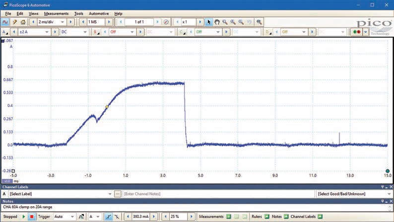
Injector Current Waveform Analysis
Voltage is applied to the injector. The current in the injector does not increase instantly but starts to rise slowly because the injector is inductive (coil).
Notice the bump at about -1 ms which is caused by the change in inductance as the pintel (plunger) moved (opens). This is very obvious in this waveform but often it is just a slight bump or change in the slope.
If the injector was purely inductive, the current would keep on rising however, the coil windings have resistance and sometimes the ECU drivers have current limiting. The current flattens out due to one or both of these factors.
Once the correct quantity of fuel is injected, the driver switches off and the current ceases flowing.
Although the current waveform shows when the injector opened, there is no information about when it closed which is why it is useful to see the voltage waveform at the same time.
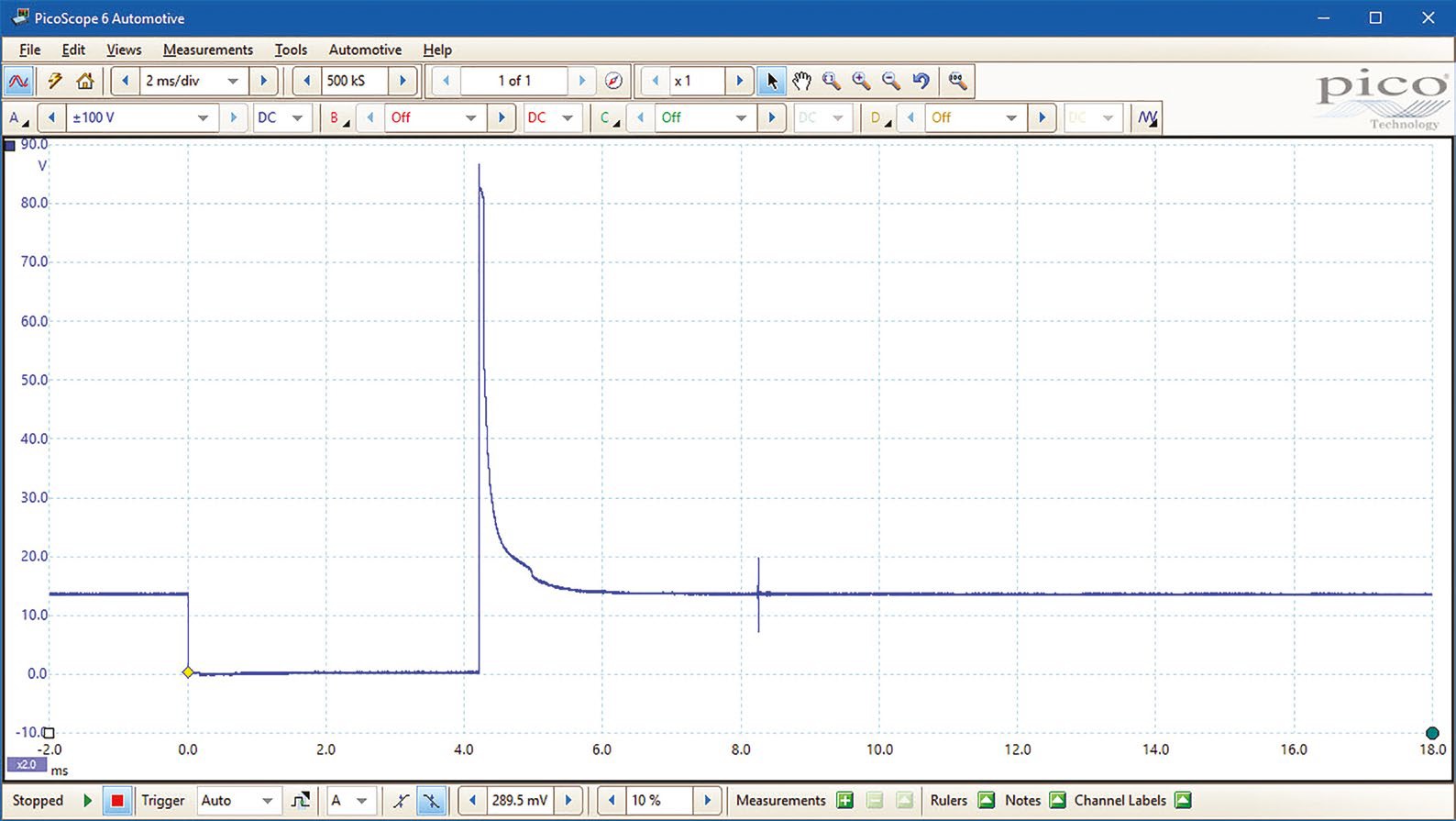
Injector Voltage Waveform Analysis
Please Note: the voltage and current waveforms shown above are from different tests so the absolute time values do not correlate.
The voltage waveform is very different to the current waveform and usually, they are displayed simultaneously. You can use Channel A for current and channel B for voltage.
The voltage goes low as the driver switches on and pulls the injector to earth.
There is no information here about the valve opening which is why it is useful to see the current waveform at the same time.
When sufficent fuel has been injected, the driver is switched off. The coil is inductive and therefore stores energy. When the current is abruptly terminated (see the current waveform above) the energy is converted into voltage which produces the large spike.
The energy dissipates (usually in flyback diodes in the driver) and the voltage spike diminishes.
Notice the little bump in the voltage after the spike (at about 5ms). This is due to the change in induction caused by the pintel (plunger) closing. Examining the two waveforms together shows exactly how long the injector was open.
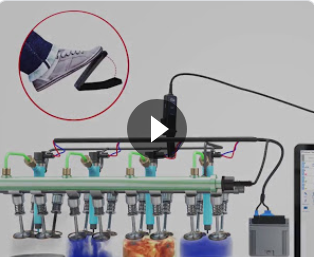
Injector Current Test Animation
Video Commentary
The video shows direct injection and if you look carefully, there were three injection event during the compression and power phases.
Connect: A current clamp is used to monitor the injector current.
Run: The engine is started and the slow motion shows (unlike the sprung injector above) the injector reciving a positive pulse to open it followed by a negative pulse to close it. This happened three times. Notice how the time between open and close pulses increases allowing more fuel to be introduced over a longer period.
Ignition occurred and the fuel was burned.
Notice the change in the waveform as the accelerator is depressed.
You can test each injector sequentially to ensure that all are working properly.
Please click Next for the fifth test - Lambda EGO Sensor Test.