
Current Clamps
Whenever an electrical current flows in a conductor, a magnetic field is generated around the conductor. The strength of the field is proportional to the current and the direction of the field depends on which way the current is flowing.
A current clamp detects that field and allows you to measure the current without breaking the circuit. For most tests, only one conductor should be measured at a time. If you try to measure current flowing to and from a device (both wires), the magnetic fields will tend to cancel each other out.
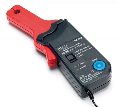
20A / 60A AC (rms) or DC, 20KHz Economy Current Clamp

The PICO-TA018 current clamp is ideal for use with PicoScope automotive oscilloscopes for measuring currents between 10mA and 60A. This enables the PicoScope to display current waveforms for fuel injectors and fuel pumps.
The current clamp has two range settings, set by a slider switch on the handle of the probe.
- 1 mV/10 mA (100 mV = 1 A)
- use this for testing currents up to 20 A.
- 1 mV/100 mA (10 mV = 1 A)
- use this for testing current up to 60 A.
In use there is no need to break into the circuit or disturb the isolation as the opening jaws simply clamp around the current carrying conductor. No electrical contact is required.
These current clamps have been designed for use with PicoScope oscilloscopes and feature additional screening to reduce noise pickup. The Pico TA018 current clamp can either be purchased as an accessory within one of our popular diagnostic kits or individually.
Connecting
The PICO-TA018 current clamp features a BNC connector and can be plugged directly into a PicoScope.
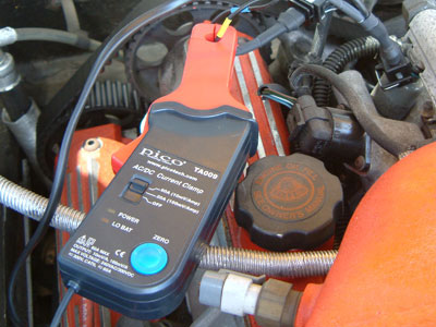
Once connected to the PicoScope, switch the current clamp on (green LED should light) and then clamp the jaws around the current carrying conductor as shown.
Documentation and Specifications
Typical Uses
The PICO-TA018 current clamp simply offers the best value for money without compromising resolution. This current clamp has multiple uses and, with a flexible measurement range from 10 mA to 60 A, the PICO-TA018 clamp is suitable for applications such as:
- Petrol and diesel injector operation
- Solenoid testing
- Throttle motor functions
- EGR actuator testing
- Broadband 02 sensor testing (in conjunction with current multiplier)
- High current consumption tests up to 60 Amps (Motor lock up test)
- Parasitic drain measurements
600A AC or DC, 400Hz Economy Current Clamp
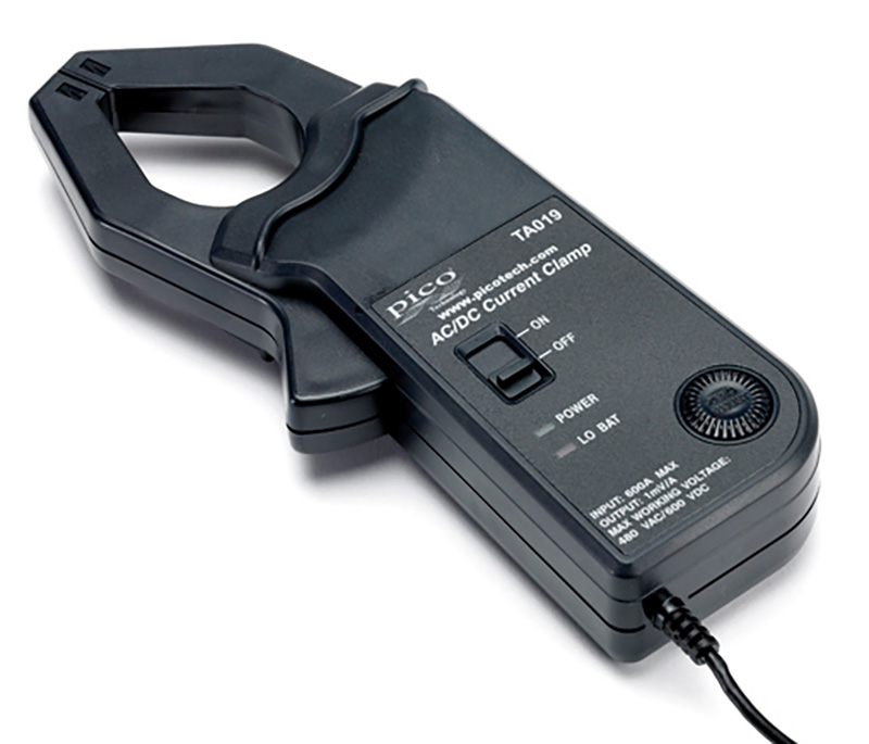
The PICO-TA019 current clamp is ideal for use with a PicoScope automotive oscilloscope to display starter current waveforms, charging currents and for performing quick compression tests.
The current clamp can measure up to 600 A (AC or DC). In use there is no need to break into the circuit or disturb the isolation as the opening jaws simply clamp around the current carrying conductor. No electrical contact is required.
These current clamps have been designed for use with PicoScope oscilloscopes and feature additional screening to reduce noise pickup.
Documentation and Specifications
Typical Uses
The size and reach of the jaws of this clamp assist you in performing tests easily. Measure the starter motor current of petrol engines, up to 600 amps. Alternator charging systems can also be evaluated (both petrol and diesel engines). The tests are non-intrusive. The PICO-TA019 clamp ensures accuracy with reduced noise levels. The following are examples of tests that can be performed with the PICO-TA019:
- Relative compression test (Petrol)
- Charging system evaluation (Petrol and Diesel)
- Battery testing with Pico Diagnostic’s software (Petrol)
- Starter motor and circuit evaluation (Petrol)
The PICO-TA019 is suitable for monitoring starter current on petrol engines. Diesel engines with their higher compression ratios tend to draw much more current when starting. Please consider our PICO-TA167, 2000A probe, for high-current applications.
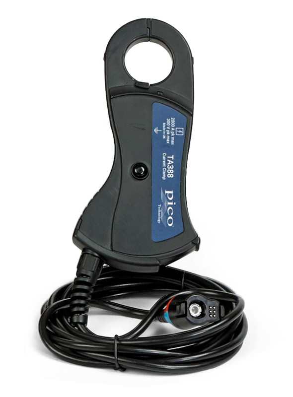
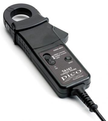
200A / 2000A DC Current Clamp
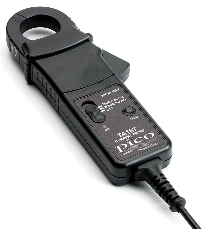
The 200 A / 2000 A current clamp allows you to measure up to 2000 amps without cutting, disconnecting or stripping wires. Simply clamp the jaws around the cable to be tested and plug the clamp into your PicoScope.
Before the launch of this probe we recommended the PICO-TA019 (600 A) for working on the starting and charging systems of petrol passenger cars and the (now discontinued) PICO-PP253 (2000 A) clamp for high compression diesel engines. The new PICO-TA167 (200 A / 2000 A) covers both of these applications in one probe with improved range and sensitivity, lower noise and faster response.
The PICO-TA167 features a 200 A mode for better resolution and performance at lower currents and has an increased jaw size. It also features an auto power-down facility to save battery life when not in use (this feature can be disabled for battery drain / shutdown current testing).
Documentation
Typical Uses
The wide range of this clamp allows currents to be measured from under 1 amp right up to 2000 amps. It can therefore be used with a PicoScope for many applications on petrol and diesel engines, including:
- Battery testing with PicoDiagnostics software
- Relative compression testing
- Starter motor testing
- Alternator output testing
- Hybrid and EV electric motor current
The 200 A range supports many applications where a "low amps" clamp would normally be required such as checking injector and ignition current.
Specifications
Electrical Data
|
(All accuracies stated at 23°C ± 1°C) |
|
| Nominal current |
2000 A AC pk max. or DC |
| Measuring range(s) | 2000 A |
| Overload capacity | 2200 A (60 s) |
| Output sensitivity | 10 mV/A and 1 mV/A switchable |
| Accuracy* (0 to 200 A of 10 mV/A) | ± 1% of reading ± 100 mA |
| Accuracy* (0 to 1500 A of 1 mV/A) | ± 1% of reading ± 500 mA |
| Accuracy* (1500 to 2000 A of 1 mV/A) | ± 5% of reading |
| Gain variation | ±0.15% of reading/°C |
| Frequency range | DC to 20 kHz (–1 dB) |
| iRMS x f ≤ 400,000 | |
| Power supply | 9 V alkaline battery PP3, MN 1604 or IEC6LR61 |
| Load impedance (minimum) | > 100 kΩ and ≤ 100 pF |
General Data
| Conductor size | 32 mm diameter |
| Output cable and connectors | 2 m long coax terminated with safety BNC connector |
| Operating temperature | 0°C to +50°C |
| Storage temperature with Battery removed | –20°C to +85°C |
Instructions
Switch on
When the probe is switched on and the required measuring range selected, the green LED will illuminate. The LED starts flashing when the battery voltage is too low for normal operation and warns you that it requires changing. This procedure is described below.
Auto power off
In order to save battery life, the probe will automatically switch itself off after approximately 10 minutes. To disable the auto power off function, switch off the probe and switch on while pressing the auto zero button. The red LED will illuminate and the probe will stay on until switched off again.
Auto zero
The output zero offset voltage of the probe may change due to thermal shifts and other environmental conditions. Select the required measuring range and then depress the Auto Zero button to null the output voltage. Ensure that the probe is away from any current-carrying conductors while the probe is being nulled.
Current measurement
- Switch on the probe by selecting the required measuring range and check that the green LED is lit.
- Connect the output lead to the oscilloscope,
- Zero the probe using the Auto Zero button.
- Clamp the jaws of the probe round the conductor ensuring a good contact between the closing faces of the jaws.
- Observe and take measurements as required. Positive output indicates that the current flow is in the direction shown by the arrow on the probe.
Battery replacement
The green or red LED will flash when the minimum operating voltage is approached. Use the following procedure:
SAFETY WARNINGBefore removing the battery cover, ensure that the probe is disconnected from the oscilloscope and remote from any live electrical circuit.
Unclamp the probe from the conductor, turn it off using the On / Off switch and disconnect the output leads from external equipment. Loosen the captive screw that secures the battery cover. Lift the cover through 30° and pull it clear of the probe body. Replace the battery, re-fit the battery cover and fasten the screw.
Fit only Type 9 V PP3 Alkaline (MN 1604).
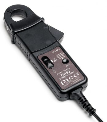
30A AC/DC Precision Current Probe

The PICO-TA189 30 A high-precision current probe is for applications requiring non-intrusive current measurement, using closed-loop Hall effect technology to measure both AC and DC current with high stability over long periods of time. Ideal for current leakage monitoring, battery discharge testing, or used in conjunction with an active differential voltage probe such as TA041, it can be used for power quality analysis.
This current clamp has the highest frequency response of the range - 100kHz
Documentation
Specifications
| PICO-TA189 30A Precision Current Probe Electrical Specifications (All accuracies stated at 23°C ± 1°C) |
|
|---|---|
| Nominal current | 30 A AC peak or DC |
| Measuring range | 30 A |
| Overload capacity | 500 A (60 s) |
| Output sensitivity | 100 mV/A |
| Accuracy | ±1% of reading ± 2 mA |
| Resolution | ±1 mA |
| Gain variation | ±0.01% of reading/°C |
| Frequency range | DC to 100 kHz (0.5 dB) |
| Safety category | CAT III 300 V |
| Power supply | 9 V alkaline battery PP3, MN1604 or IEC 6LR61 |
| Load impedance (minimum) | > 100 k and 100 pF |
| General data | |
| Conductor size | 25 mm diameter |
| Output cable and connectors | 2 m long coax cable with safety BNC connector |
| Operating temperature | 0°C to +50°C |
| Storage temperature with battery removed | –20°C to +85°C |
Current Clamp Feature Comparison
|

|
|
|
||
| Part Number | PICO-TA018 | PICO-TA019 | PICO-TA167 | PICO-TA189 | |
|---|---|---|---|---|---|
| Current | 20/60A | 600A | 200/2000A | 30A | AC peak or DC |
| Frequency | 20 | 0.4 | 20 | 100 | kHz |
| Overload | 60A | 600A | 2200A (1 min) | 500A (1 min) | AC Peak or DC |
| Sensitivity | 100/10 | 1 | 10/1 | 100 | mV/A |
| Conductor | 9 | 30 | 32 | 25 | mm dia |
Please note that this is a rough overview for comparative purposes only. Please refer to the individual devices' specifications.


