Injector Waveform - High Speed with Regulation
Understand high speed injector waveforms with switch-mode current regulation. We analyse waveforms captured by a PicoScope showing injector current and voltage from idling diesel engines.
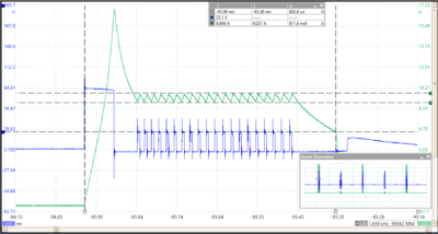
The vehicles' waveforms shows cycles with two pilot pulses followed by a main pulse. Pilot pulses are used to even out diesel delivery during idle, which reduces the intensity of detonation in the cylinder. That, in turn, reduces the annoying and characteristic knocking noise, often heard when older diesel engines are idling.
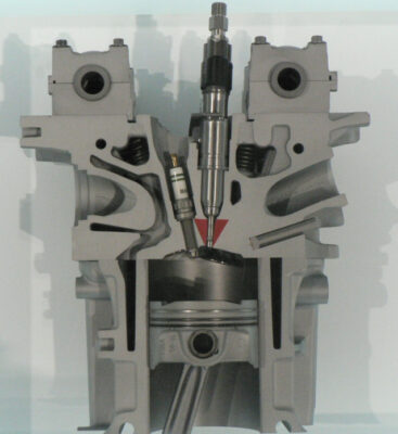
An electrically operated injector is, in reality, a solenoid valve. When current passes through the coil, a plunger moves and the valve opens. Relays and solenoid actuators also work using the same principle.
Background and Principles
When current passes through the injector's coil, it creates a magnetic field that moves the plunger. Increasing the current increases the intensity of the magnetic field. In just the same way as a starter motor needs much more current to start the engine moving than when the engine is turning, a solenoid needs more current to start the plunger moving and much less current (about half) to hold it open.
Injector Speed
Where multiple injector pulses are required for each cycle, the injector needs to open and close very quickly - the entire cycle can be much less than 1ms (a thousandth of a second). Lots of current is required to open the injector at that speed but if that high current level persisted throughout the open period, the coil would heat up (and possibly burn out) and energy would be wasted.
Ideal injector driver
The ideal driver would provide masses of current initially to open the injector as quickly as possible. Once the injector has opened, the current would be allowed to reduce to a much lower holding level to keep the injector open. When the injector needs to close, the current in the coil needs to stop as quickly as possble.
How an inductor works
Very much like a fly-wheel, when a voltage is applied to an inductor (the coil in an injector) the current does not rise instantly but increases slowly as it builds up the magnetic field. When the applied voltage is removed, the current decreases slowly as the magnetic field collapses. This is the reason for the huge voltage spike in systems such as ignition coils when the points are opened and the current has nowhere to go.
Current = Voltage multiplied by Time divided by Inductance
First Vehicle Injector Waveform
The injector waveform was captured from a 4 litre, four-cylinder diesel engine with a 24V battery.
Opening quickly
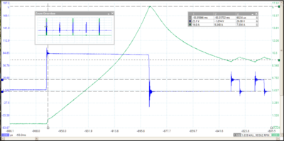
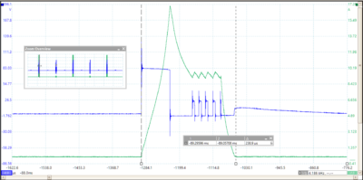
From the formula above, if the voltage is increased, the current in the inductor increases more quickly. The voltage applied to the coil in the waveform under discussion when opening the injector is about 84V, much higher than the 24V available from the battery. That voltage was probably generated by a DC to DC boost converter in the ECU and supplied from a charged capacitor. Note the small voltage droop as the current builds up to 16 Amps.
In the injector waveform above, the injector probably opened at about 10.3A as the rate of increase (steeper slope) of the current changed. When the plunger moves, the inductance of the injector changes (usually lower when it opens) and this change can provide an indication that the plunger has moved and opened.
As soon as the current reaches the desired pull-in level (about 16A) the ECU switches off the voltage. The current continues to circulate through free-wheeling diodes in the ECU. That is why the voltage between the pulses goes slightly negative (about -1.8V).
Regulation of Holding Current
We need to consider ways to control and limit the current. Switching regulators are efficient, run cool and are ideal when used to control current in an inductor.
The 24V pulses are used to regulate the holding current. When the current drops to about 9A, the ECU switches on a 24V pulse. Current immediately starts to rise. Once the upper level of about 9.8A is reached, the ECU switches off the pulse and the current starts to fall again. Thus, an average holding current of about 9.4A is maintained whilst the injector is open.
Closing must also be quick
In order to close an injector quickly, the current needs to reduce as quickly as possible. One technique would be to short circuit the coil. Another, even quicker method would be to reverse the voltage applied across the coil. A low holding current is an advantage here as the magnetic field is less intense and therefore less current (or energy) needs to be disposed of.
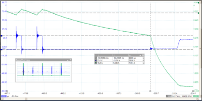
In the injector waveform above, at the end of the cycle, there is a sharp change in the negative slope of the current waveform. It seems that the ECU reverses the voltage across the coil to force the magnetic field to collapse and to close the injector quickly. There is a delay before this happens in the pilot pulses but in the main pulse (see below), the reversal occurs immediately.
First Vehicle Notes
There are three injector pulses per cycle. The main pulse is much shorter - the engine was idling and did not need much fuel (see the waveform below). The total width was only 240us. However, four-and-a-half holding current regulation pulses are used. Notice how the last pulse is truncated because the injector needs to close. Thus, it is clear that this system can support even shorter injector open times.
Zoom in!
This injector waveform shows the fine detail that can be revealed by using your PicoScope. This capture had 25 million samples (far less than the PicoScope's full sample buffer capacity of 250 million samples). We have zoomed into one of three injector pulses.
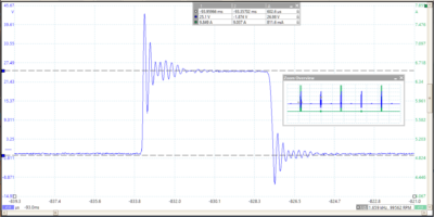
However, there is even more detail available. The waveform above zooms into the first 24V pulse used to regulate the holding current. Notice the detail available in the ringing waveforms on the leading and trailing edges of the pulse. See Which Scope is Best for more.
Second Vehicle Waveform
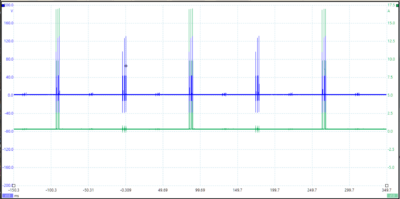
The waveform above shows the voltage being monitored on one side of the injector coil. In order to achieve high speed, modern ECUs often drive both sides of the coil using an H-bridge. That means that when you are testing high-speed injectors, you should monitor the voltage on both sides of the coil.
An H-bridge has four switches that can connect either side of the injector to positive or to ground which allows the voltage to be reversed. Extra positive switches (H legs) allow the injector to be connected to the higher voltage needed to speed up opening and closing.
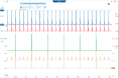
The following waveforms were captured from a BMW 320 d with Bosch Solenoid injectors by Steve Smith at Pico using the new PicoScope 7 Software.
PicoScope Channels
- Channel A Voltage on the positive-to-close side of the coil.
- Channel B Voltage on the-positive-to-open side of the coil.
- Channel C Current through the coil.
- Channel D Voltage across the coil using a differential probe.
If you do not have a differential probe, you can easily setup a maths channel and subtract channel A from channel B (B - A) to achieve the same result.
Zoom into One Injector Pulse
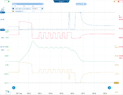
The BMW has a 12V battery, however, channel B (positive-to-open) is very similar to the voltage waveform above. An initial high voltage pulse around 40V is followed by a number of current regulator pulses.
Note how Channel A goes high, one pulse firstly to reduce the current near the end and then a longer pulse with Channel B ground to close the valve.
That results in the Channels C and D waveforms. A high voltage initial pulse causes the current to rise rapidly. Smaller regulating pulses maintain the current at just below 10A. The short 'negative' pulse in channel A drops the current in preparation for closure and then, the longer pulse on Channel A stops the current quickly by applying -42V across the coil.
Additional Notes
Steve and I discussed possible reasons for the delay in applying the negative pulse on pilot cycles on the first vehicle. A similar reduction in current can be seen in the BMW waveform (resulting from the short 'negative' pulse). He suggested the following possible reasons:- Improved control of the pintle valve (progressive closing)
- A strategy surrounding finite control of the coils “reactance” to rapidly switching current during the holding stage.
- To allow a degree of cooling (down time).
- Promote lubrication of the pintle valve.
- Engineers may have determined that such a strategy supports the up and coming Pilot and Main injection events (Either from an electrical or mechanical point of view).
He believes that point 5 above is what we are seeing with the Pilot injection event (events 2). The decay period is interrupted with further control of the pintle closing which could well introduce a unique and optimal spray pattern prior to seating of the pintle valve
Finally, the Main injection event (event 3) has the abrupt closure as you would expect, given that no more fuel must be injected for another 720° of crank rotation (approx.)
Injection Strategy
All of the injector waveforms above were obtained during engine idle. The injection strategy of course will change during engine load, acceleration, over-run and during DPF regeneration, where the main injection event is no longer the final event in the 4 stroke cycle as the injector can be pulsed during the exhaust stroke to increase DPF temperature.

