
Test 9 - CAN Bus Test
The CAN Bus or Controller Area Network Bus is a high-speed differential signal bus (the difference is taken between the two bus conductors to reduce or eliminate common-mode noise) which carries messages around the vehicle.
It is a robust vehicle bus standard designed to allow microcontrollers and devices to communicate with each other's applications without a central host computer.
It is a message-based protocol, designed originally for multiplex electrical wiring within automobiles to save on copper. For each device the data in a frame is transmitted sequentially but in such a way that if more than one device transmits at the same time the highest priority device is able to continue while the others back off. Frames are received by all devices, including by the transmitting device.
For more advanced information see our article on CAN Bus Testing using Maths Channels.
- Software: PicoScope 6 - Guided Test AT126
- Purpose of Test - Dual trace testing of CAN-High and CAN-Low Signals
- Skill Level Required - Intermediate
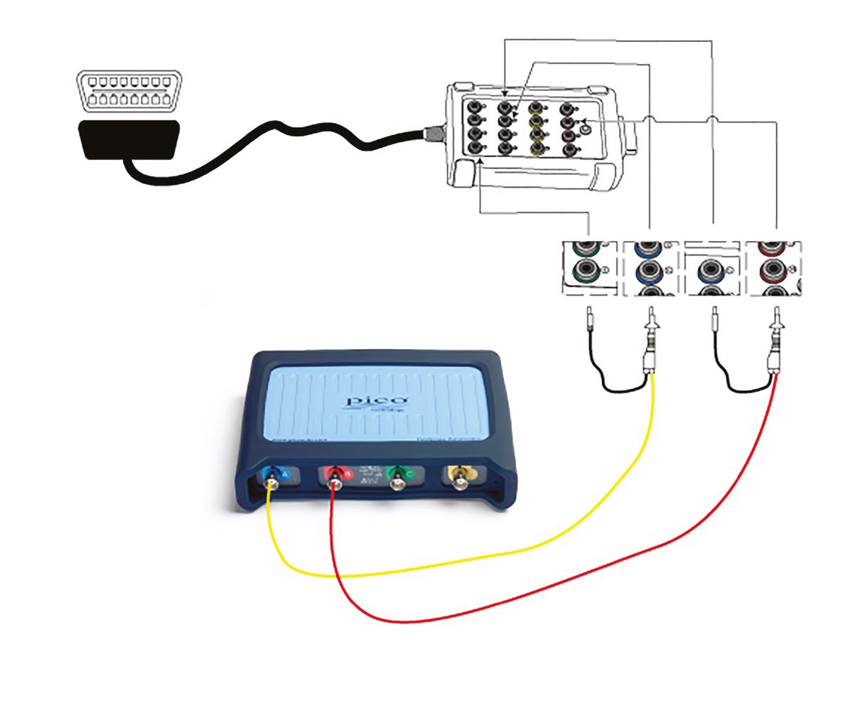
Connect: We recommend using our CAN Test Breakout box to make a secure connection to the vehicle’s communication signals. When it is connected to the vehicle’s diagnostic socket, the LEDs on the breakout box will light up to indicate that there is activity on the bus. Connect the yellow lead to Channel A of the scope and to pin 6, then the black pin to pin 4 (Chassis GND). Connect the red lead to Channel B of the scope and to pin 14.
Note: Some vehicles can have multiple CAN connections on the 16-pin connector, and some vehicles may use pin 5 (Signal GND) instead of pin 4.
Run: Start PicoScope and turn on the vehicle ignition. You should now see a waveform.
Read: The waveform should reveal to you that data is being exchanged continuously along the CAN bus. It is also possible, of course, to check that the peak voltages are correct.
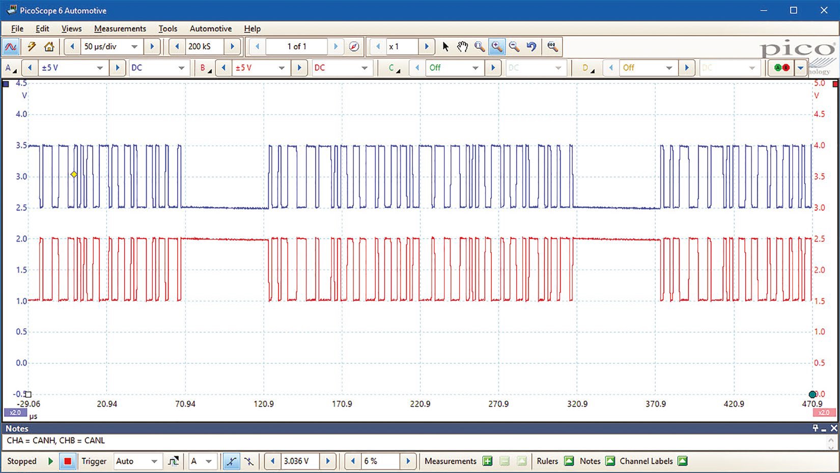
Waveform Analysis
The data is sent in packets. The waveform shows the end of a packet followed by full packet and then the start of a third packet. CAN high and low are nominally at 2.5V which is logic 1 or the recessive state. When a logic 0 or dominant state needs to be sent, CAN high is pulled up to 3.5V and CAN low is pulled down to 1.5V.
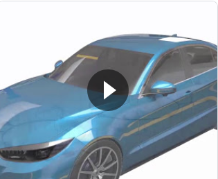
CAN Bus Test Animation
Video Commentary
The Video shows how the CAN Bus is connected to many components throughout the vehicle. It can be used to also talk to controllers that relay messages to another bus such as a LIN bus. There may be more than one CAN bus.
Connect: The easiest way to access the CAN bus to via the vehicle service OBD port inside the vehicle. Use a CAN breakout box to connect to it. Connect the yellow lead to Channel A of the scope and to pin 6, then the black pin to pin 4 (Chassis GND). Connect the red lead to Channel B of the scope and to pin 14.
Run: Start PicoScope and turn on the vehicle ignition. You should now see a waveform.
Read: The waveform should reveal to you that data is being exchanged continuously along the CAN bus.
Advanced Testing: You can ask the PicoScope to decode the CAN data for you by using the Serial Decoding facility built into the PicoScope software.
Please click Next for the Tenth test - Cylinder Compression Test.