
CAN Bus Testing with PicoScope 6
Also see the Can Bus Test on our training website.
The examples in the Maths Channel Basic Tutorial might look contrived but they can be very useful. Use A * B to determine the instantaneous power in a circuit if one of the channels is a current and the other a voltage: V * I = P. You can even choose Watts as a unit. The maths channel can be an extremely useful tool when analysing a CAN network.
CAN Bus Signals
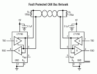
CAN is a digital, differential signal bus. A stream of 1s and 0s is sent along two wires.
Logic 1
When a logic 1 (called the recessive state) is sent, both output drivers in the sending device are switched off. As a result, terminating resistors cause both lines to settle at 2.5V.
Logic 0
When a logic 0 (called the dominant state) is sent, both output drivers switch on. The high-side CAN-H driver pulls its line high (to about 3.5V) and the low-side CAN-L driver pulls its line low (to about 1.5V).
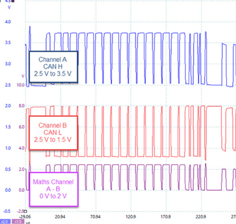
The CAN receiver recovers data by subtracting the voltage on CAN-L from the voltage on CAN-H. That means that when a 1 (recessive) bit is sent, the difference is 0V. When a 0 (dominant) bit is sent the difference is 3.5 – 1.5 = 2V. A subtracting PicoScope Maths Channel can be used to reject CAN bus noise and extract the signal just like a conventional CAN receiver.
Noise Rejection
The question arises – why use two wires to send the same information? The answer is noise immunity. Any external noise (usually created by an electric or magnetic field) can be superimposed on a conductor and can destroy the data. If 5V of noise was added to a single-ended (single wire) transmission, it would swamp the data and errors would result.
| Logic Level | Nominal Voltage | Noise | Actual Voltage | Receiver | Noise | ||
|---|---|---|---|---|---|---|---|
| CAN-H | CAN-L | CAN-H | CAN-L | A - B | A + B | ||
| 1 | 2.5V | 2.5V | 0V | 2.5V | 2.5V | 0V | 5V |
| 0 | 3.5V | 1.5V | 3.5V | 1.5V | 2V | 5V | |
| 1 | 2.5V | 2.5V | +5V | 7.5V | 7.5V | 0V | 15V |
| 0 | 3.5V | 1.5V | 8.5V | 6.5V | 2V | 15V | |
| 1 | 2.5V | 2.5V | -5V | -2.5V | -2.5V | 0V | -5V |
| 0 | 3.5V | 1.5V | -1.5V | -3.5V | 2V | -5V | |
The two CAN wires should be (and usually are) twisted together and therefore any extraneous noise is added to both wires at the same time. The receiver cancels the noise out by subtracting the signals.
Even in the presence of ±5V of noise on each signal wire (which is 10 times the amplitude of the data) the receiver will recover the data without any errors. As a result, all ‘common mode’ noise (superimposed on both lines) is cancelled (provided that the receivers can handle the high common mode voltage).
Isolating any Errors or Noise
As can be seen from the table above, the sum (CAN-H + CAN-L) of perfect CAN bus signals is a constant 5V for both 1s and 0s. Therefore, if you create a maths channel that adds the two signals together, any deviation from 5V is twice the amplitude of any noise or error voltage on the CAN bus. The data is effectively filtered out of this noise maths channel which allows you to track down any noise source more easily.
Single Wire CAN (SAEJ2411)
CAN is possible over a single wire. It is used in short distance, low speed applications such as 'comfort' systems and EV battery charging communications. It has severe disadvantages compared to two-wire CAN:
- Firstly there is no inherent noise immunity derived from the differential signals in conventional CAN. Any noise impressed upon the wire distorts the data; and
- Secondly, it is limited to very low speeds: 33.3kbit/s in normal operation and 83.3kbits/s in diagnostic mode (used, almost exclusively, in production).
Signal Levels
Single Wire CAN (SWC) is similar in polarity to CAN High but the levels are different. When the line is high (typically 4V) then a dominant bit (Logic 0) is being sent. When the line is low (typically 0V) then a recessive bit (Logic 1) is being sent. A Single Wire CAN receiver typically recognises a dominant bit as being below 650mV and a recessive bit as being above 2V.
You can use your PicoScope to decode Single Wire CAN data. Suggested Settings:
- Invert: Off;
- Threshold: 1.325V (halfway between 2V and 0.65V);
- Total Hysteresis: 1.35V (threshold + 675mV = 2V and threshold - 675mV = 650mV);
- Baud Rate: 33.3 kBd; and
- High or Low: High.
Physical
In SWC, an unshielded single wire is used to provide communications and up to 32 devices can be attached to the network.
Transceiver Specifications
Typical Single Wire CAN Tranceivers include the Melexis TH8056 and the NXP MC33890.