
Test 6 - ABS Sensor Test
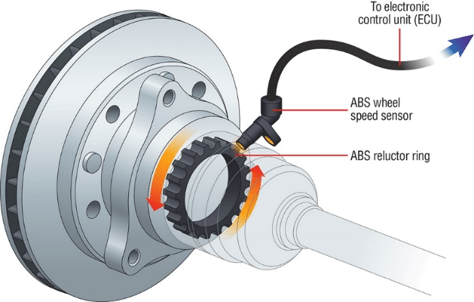
ABS Sensor Test background. The ABS Sensors monitor the rotational speed of each wheel. The sensors usually output pulses that increase in frequency as speed increases.
- Software: PicoScope 6 - Guided Test AT072
- Purpose of Test - ABS Wheel Speed Sensor Integrity
- Skill Level Required - Easy
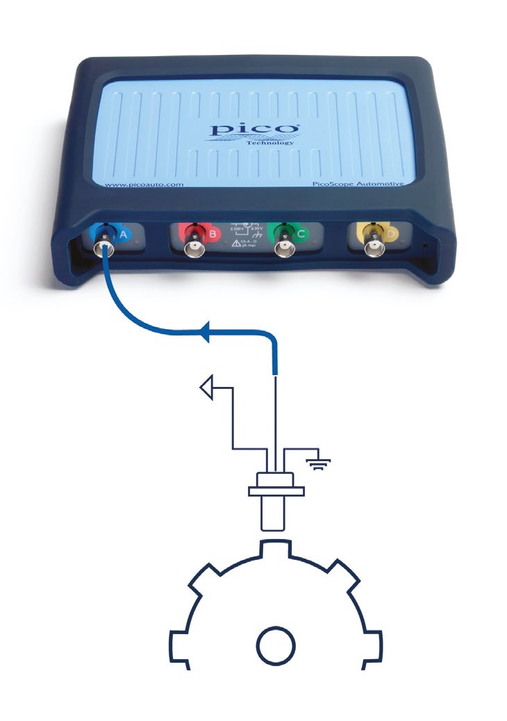
Connect: Locate the wheel speed sensor signal wire. Use the vehicle’s technical data. Where possible, we recommend you measure the wheel speed signal at the ABS control unit using back-pinning probes.
Connect the coloured test lead to the wheel speed signal wire and the black test lead to vehicle ground. In cases where the ABS control unit is not accessible, the breakout leads will allow for connection directly to the ABS sensor or sensor “fly lead”
Run: Start PicoScope and rotate the relevant road wheel in order to obtain a speed signal. (There will be no speed signal when the road wheel is stationary.)
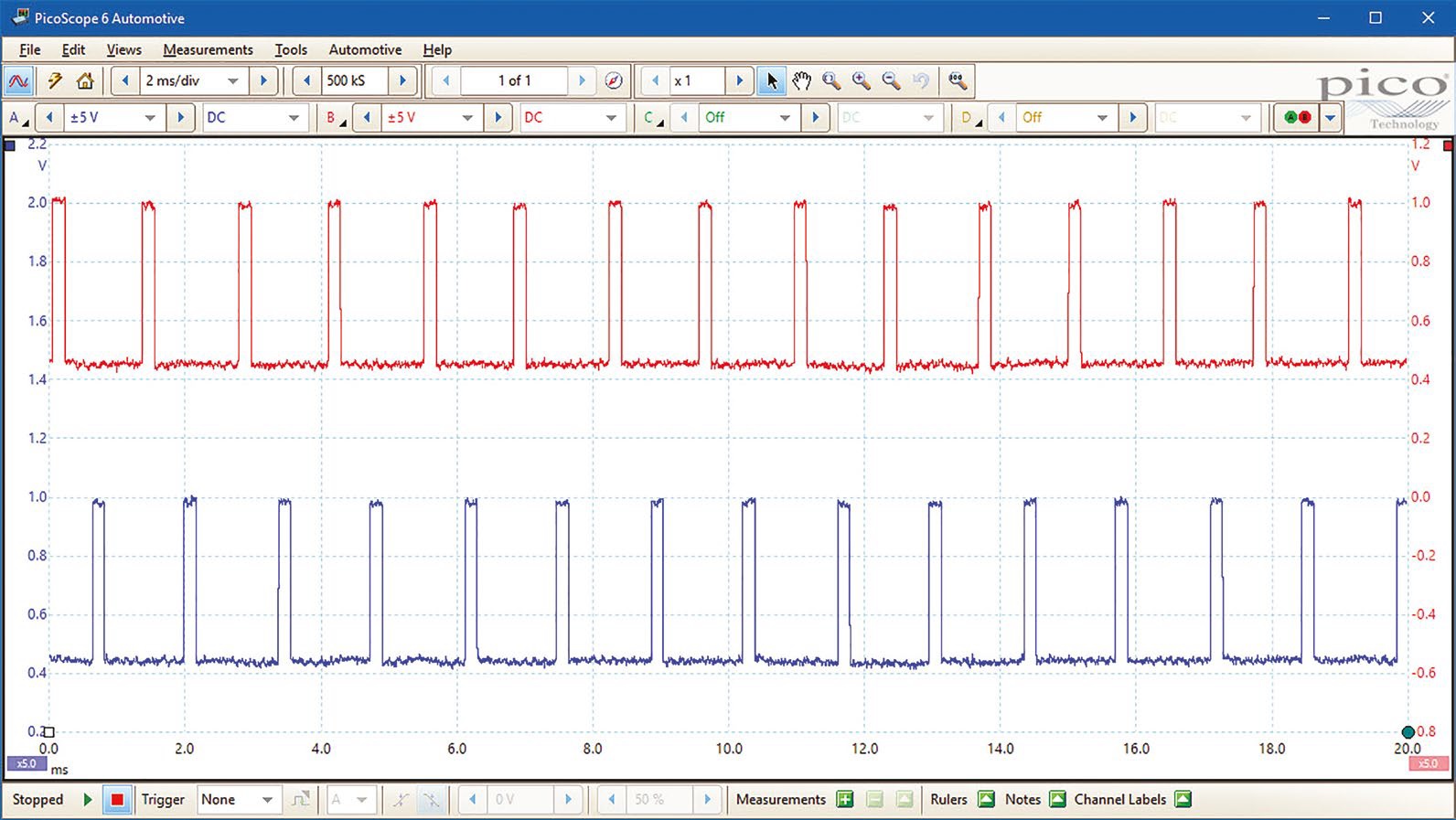
Read: As the wheel rotates, a stable and consistent waveform will be displayed by PicoScope. The frequency of the captured waveform will change in relation to the speed of wheel rotation (the frequency will increase as wheel speed increases and vice versa).
Inspect the waveform for uniformity across one complete revolution of the road wheel. The wheel speed signal should remain stable and uniform throughout each revolution of the wheel at a fixed speed. PicoScope will reveal anomalies such as poor signal formation, reduced amplitude and sequential changes to each pulse that could reveal ABS pick-up damage.
For more advanced information see our article on Using a Maths Channel to determine Vehicle Speed from ABS.
Waveform Analysis
Two ABS sensors are being monitored. The pulses vary in frequency as the rotational speed changes.
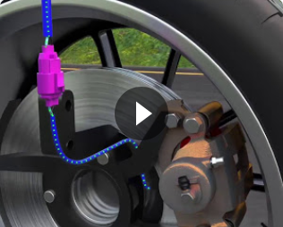
ABS Sensor Test Animation
Video Commentary
The video starts by showing a vehicle driving along the road. The ABS sensors send rotational speed information from each wheel to the controller. The sensor detects teeth and sends a pulse whenever a tooth passes it.
Connect: Locate the wheel speed sensor signal wire. Connections can usually be made using a backpinning probe. Ground the test lead.
Run: Start PicoScope and rotate the relevant road wheel in order to obtain a speed signal.
Read: The frequency of pulses will increase as the speed increases. Test each wheel. Notice the distortion of the signal from the second wheel tested.
Please click Next for the seventh test - Cam Crank Synchronisation Test.