
Test 8 - Mass Airflow Sensor (MAF)
A mass airflow sensor (MAF) is used to determine the mass flow rate of air entering a fuel-injected internal combustion engine.
The mass-of-the-air information is necessary for the engine control unit (ECU) to balance and deliver the correct fuel mass to the engine. Air changes its density with temperature and pressure.
In automotive applications, air density varies with the ambient temperature, altitude and the use of forced induction (e.g. turbo), which means that mass flow sensors are more appropriate than volumetric flow sensors for determining the quantity of intake air in each cylinder.
There are two common types of mass airflow sensors in use on automotive engines. These are the vane meter and the hot wire. Neither design employs technology that actually measures air mass directly. However, with additional sensors and inputs, an engine's ECU can determine the mass flow rate of intake air.
- Software: PicoScope 6 - Guided Test AT151
- Purpose of Test - Examine how the MAF Signal Changes
- Skill Level Required - Easy
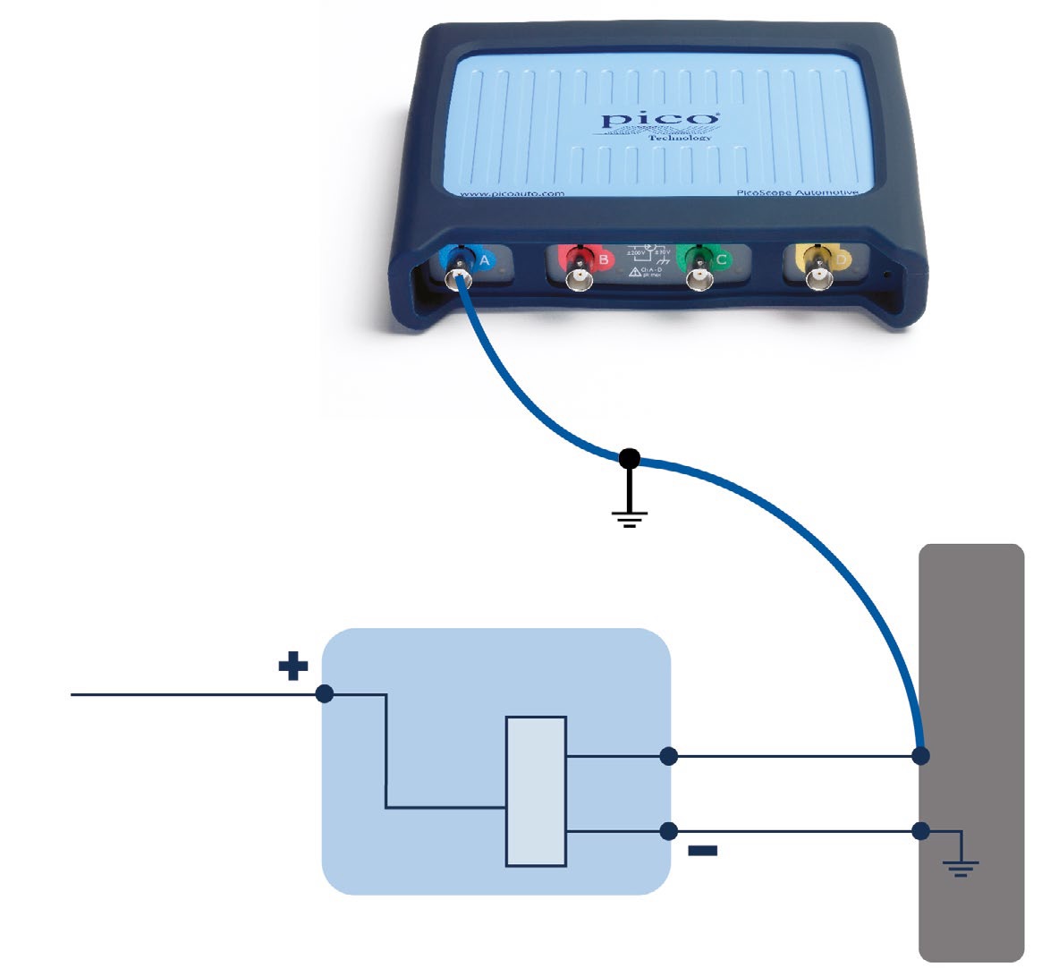
Connect: Locate sensors with the help of your vehicle’s technical data. We recommend you use either back-pinning probes or breakout leads to make the connection. Use the technical data to identify the signal wire. You can choose to check multiple terminals to obtain a signal.
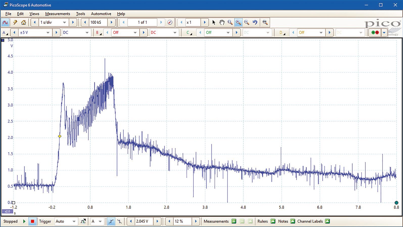
Run: Start PicoScope, and snap the throttle quickly from idle to full throttle to capture the waveform. We suggest a timebase of 1 s/div to capture 10 seconds of data in one frame.
Read: The voltage output from the air flow sensor should be proportional to air flow. The waveform should show approximately 0.5 volt when the engine is at idle, but this voltage will rise as the engine is accelerated, to around 4.0 to 4.5 volts. This voltage will, however, depend on how hard the engine is accelerated, and a lower voltage is not necessarily a fault within the air flow sensor.
On deceleration the voltage will initially fall as the throttle is closed, reducing the air flow as the engine returns to idle speed. Further details are covered in our Guided Tests.
Waveform Analysis
The effect of the greater airflow can be clearly seen. Notice how quickly the sensor reacts to the drop-off in airflow when the throttle is closed. The airflow doesn't return to its previous value immediately, probably because the engine speed is higher after the event, using more air than when idling beforehand.
MAF Snap Throttle Test Animation
Video Commentary
The Mass Airflow Sensor is shown mounted between the air filter and the inlet manifold. It produces a signal that is sent to the ECU
Connect: A backpinning probe can be used to connec to to the signal. The video shows how you can find the signal through trial and error but rather refer to the vehicle's documentation for the correct connector and pin number.
Run: Start PicoScope and the engine. Snap the throttle quickly from idle to full throttle to capture the waveform.
Read: The voltage output from the air flow sensor should be proportional to air flow.
Please click Next for the ninth test - CAN Bus Test.