
Test 3 - Wiring Loom Connection Faults
NOTE: Always use a PICO-TA197 Attenuator or the new PICO-TA499 10:1 Scope Probe and Adaptor when testing ignition primary to protect the oscilloscope inputs.
PicoScope captures data so fast it is easy to identify wiring loom or connection fault issues quickly. Simply wiggling a wire (arguably an easy test that can often be overlooked) can reveal a wiring fault.
- Software: PicoScope 6
- Purpose of Test - Wiring Loom or Connection Faults
- Skill Level Required - Very Easy
Connect: This test is used when you suspect or have spotted an intermittent fault with a signal (so a connection is already made).
Run: Start PicoScope when you are ready to capture the signal and gently wiggle the wiring loom attached to the component.
We recommend reducing the capture rate to make it easier to spot problems within a single screen capture. Masks and alarms can be used to automate detection when signals go outside normal limits.
Read: Stop PicoScope and scroll back through the data with the buffer controls. Often wiring or connection faults will create an inconsistent pattern as illustrated in the example. When we scrolled back through our captured data, it was easy to spot the signal faults from the ignition coil. In this example, it turned out that a fault in the wiring loom was causing an ignition misfire.
Remember to retest after the repair, to make sure that you have a reliable fix.
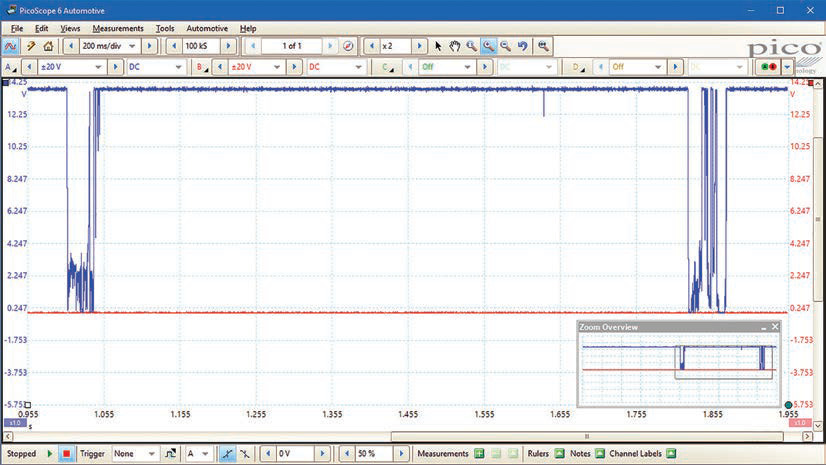
Waveform Analysis
This is a very simple waveform showing disturbances due to an intermittant connection. The problem is obvious.
As an aside, notice the zoom feature. You can zoom into portions of the waveform to see greater detail. The massive buffer, 12-bit resolution and high sample rate of the PicoScope allows you to examine events in minute detail.
Intermittent Wiring Test Animation
Video Commentary
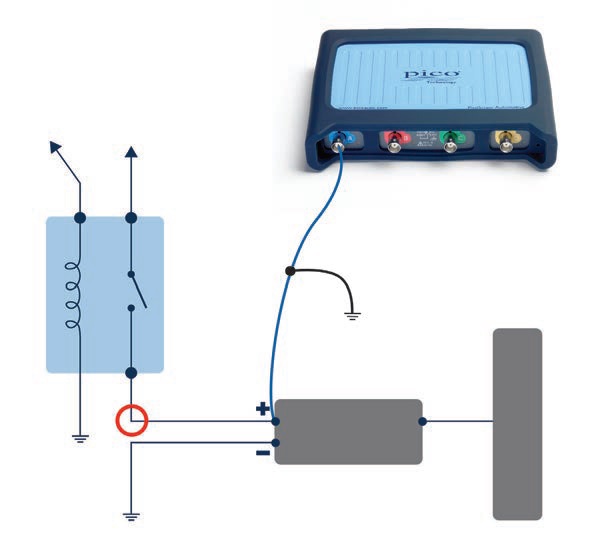
In this test, the Camshaft sensor seems to be faulty but intermittant.
Connect: Use a Backpinning Probe to connect to the Camshaft Sensor and ground the test lead as shown.
Run: Start PicoScope and the engine when you are ready to capture the signal and gently wiggle the wiring loom attached to the component.
We recommend reducing the capture rate to make it easier to spot problems within a single screen capture. Masks and alarms can be used to automate detection when signals go outside normal limits.
Read: Stop PicoScope and scroll back through the data with the buffer controls. Often wiring or connection faults will create an inconsistent pattern as illustrated in the example. The loom was compromised by chafing against a bolt causing an intermittant connection and short to earth.
Remember to retest after the repair, to make sure that you have a reliable fix.
Please click Next for the fourth test - Injector Test.