
Compression Testing
The compression test is meant to be the first check. If the compression looks good, you can quickly move on to investigate other potential causes. If the test detects a low cylinder, you should perform a manual compression test to verify the data and determine the faulty cylinder.
Relative Compression Testing

With a relative compression test, you can easily determine if all the cylinders in an engine have equal compression. This test is a quick check on compression that you can do without removing the spark plugs or glow plugs. It uses the starter motor current to determine the comparative compression values on all cylinders.
The advantages of doing this test are that you do not need a pressure transducer/sensor to run the test, all you need is a scope and a current clamp and that you do not have to check each individual cylinder, all cylinders can be tested in one go.
The theory behind the relative compression test is that the amount of current required to turn over the engine while a cylinder is on its compression stroke will indicate how much the cylinder is compressing or leaking. This will information makes sense when you compare all the cylinders, as you can easily see if one is weaker than the others.
It is important to remember to prepare the vehicle for testing so that the engine will not start during cranking.
In the relative compression test in PicoDiagnostics, the result is scaled to show the highest cylinder as 100%. The bars are displayed in the engine’s firing order and they are named A, B, C, and so on. With only the battery connection, the software cannot determine which cylinder is number one, so the result could shift if you run the test more than once.
Absolute Compression Testing

If you have a low reading in the results from the relative compression test, the next step is to introduce the WPS500X Pressure Transducer and perform an in-cylinder compression test.
The software evaluates the cylinder efficiency in an engine through 720 degrees crankshaft rotation to gain a peak cylinder pressure. All you have to do is remove one spark or glow plug and insert the pressure transducer.
There is some extra setup required before you can carry out the test. As we are now measuring ‘pressure’ we need to tell the software we are doing so. Click the pressure button.This will give you a number of options and the more information that can be filled in the more accurate the results will be.
In the absolute compression test, PicoDiagnostics will display the true compression in each cylinder. The bars are named A, B, C, and so on.
In-cylinder Testing with the WPS500X
All values included in the example waveforms are typical and not specific to all vehicle types.
The WPS500X pressure transducer simply provides a means to convert positive or negative pressures into voltage. When combined with PicoScope, you have the distinct advantage of displaying pressure values against time. This gives the technicians the ability to view dynamic changes in cylinder pressures during the four-stroke cycle. If you assess the cylinder efficiency with the WPS500X, you can reveal additional information about the condition of your engine and the individual valve timing. Because of the resolution and speed of the pressure transducer and PicoScope, you can see more than ever thought possible. For this reason, we have to be aware that the variety of engine designs, intake, exhaust systems, and elaborate variable valve timing will all have an effect on the waveform/results which will differ from vehicle to vehicle.
The rotation rulers are used to denote 0 and 720 degrees of rotation for the captured cylinder pressure waveform. Given that peak cylinder pressure occurs at TDC of the compression stroke, you can position the rotation rulers at two consecutive compression towers to denote 0–720 degrees of crankshaft rotation relative to TDC/peak compression.
Based on our knowledge of the four-stroke cycle, we know the events that should take place between the rotation rulers at 0 and 720 degrees (TDC Compression to TDC Compression).
To make the diagnosis easier, you can divide the distance between 0 and 720 degrees into four equal divisions to reveal the position of the crankshaft at key stages throughout the four-stroke cycle (TDC and BDC).
Once we know the position of the crankshaft, we can identify each of the four-stroke cycles between compression events and attributing anomalies found to specific four-stroke events/activities.
Based on the cylinder efficiency test and analysis procedure in the Guided Test In-cylinder compression – cranking (petrol), we can confirm the following:
- Correct peak cylinder pressure for the engine under test. Allow for standard compression hose volume of 5ml.
- Uniform and symmetrical compression towers confirming the cylinder efficiency, not only as the pressure builds but also as it naturally decays during the expansion stroke. For the compression towers to be symmetrical, the valve timing, valve train and mechanical integrity of the piston/cylinder must be efficient.
- The presence of the expansion pocket confirms that our cylinder can hold a vacuum and must, therefore, be airtight (the integrity of the valve seat and piston ring is OK).
- Sufficient cranking speed.
- Adequate intake and exhaust flow to achieve the correct peak pressure (no restrictions).
- Repeatability of peak compression for every completion of the four-stroke cycle.
- Cylinder pressure remains at zero bar during exhaust and intake events which confirms there are no airflow restrictions during either stroke.
Based on the cylinder efficiency test and the analysis procedure in the Guided Test In-cylinder compression – idle (petrol), you can confirm the following:
- Correct peak cylinder pressure at idle speed when compared to adjacent cylinders. Allow for the Pico standard compression hose volume of 5ml.
- Uniform and symmetrical compression towers confirm the cylinder efficiency, not only as the pressure builds but also as it naturally decays during the expansion stroke. For the compression towers to be symmetrical, the valve timing and duration, the valve train, and the mechanical integrity of the piston/cylinder must all be efficient.
- The presence of the expansion pocket confirms that the cylinder can hold a vacuum and that it must, therefore, be air tight (the integrity of the valve seat and piston ring is OK).
- Correct exhaust valve timing and duration based on the transition in cylinder pressure at approximately 180 and 360 degrees of crankshaft rotation. Refer to the vehicle repair manual for exhaust valve timing and duration.
- The integrity of the exhaust system based on cylinder pressure during the exhaust stroke (approximately 180 to 360 degrees of crankshaft rotation). Catalyst restrictions will be revealed with excessive positive pressure above 0 bar.
- Event timing at approximately 360 degrees of the crankshaft rotation by observing the valve overlap. Both the exhaust and the intake valves will momentarily remain open (refer to vehicle repair manual for valve timings and duration).
- Correct intake valve timing and duration based on the transition in cylinder pressure at approximately 360 and 540 degrees of the crankshaft rotation (the intake pocket). Refer to the vehicle repair manual for the exhaust valve timing and duration.
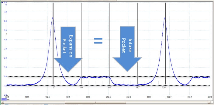
- Equal depth (vacuum level) between the expansion and intake pocket, revealing an efficient balance between the expansion and intake strokes. Manifold pressure (vacuum) is proportional to the swept volume of the cylinder by the piston, and therefore, the vacuum produced by the piston in a sealed cylinder during the expansion stroke (expansion pocket) should be near equal to the vacuum produced during the intake stroke acting against a closed throttle (intake pocket). This will vary with high-performance engines.
- Engine speed, based on 360 degrees of crankshaft rotation.
- Correct cylinder pressures during 720 degrees of crankshaft rotation (no restrictions) achieved by adequate intake and exhaust flow.
- Repeatability of peak compression for every completion of the four-stroke cycle.
Rotation Rulers and Partitions
In PicoScope, you can divide the distance between compression events into four equal partitions, revealing the position of the crankshaft (degrees of rotation) with the rotation rulers and the partitions. If we know the position of the crankshaft we can identify each of the four-stroke cycles between compression events.
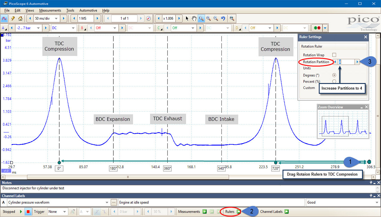
The rotation rulers are used to denote 0 and 720 degrees of rotation about the captured cylinder pressure waveform. Given that peak cylinder pressure occurs at TDC of the compression stroke, positioning the rotation rulers at two consecutive compression peaks/towers will denote 0–720 degrees of crankshaft rotation relative to TDC / peak compression. Based on our knowledge of the four stroke cycle, we know the events that should take place between the rotation rulers at 0 and 720 degrees (TDC Compression to TDC Compression). To assist with diagnosis, dividing the distance between 0 and 720 degrees into four equal divisions will reveal the position of the crankshaft at key stages throughout the four-stroke cycle (TDC and BDC). Once we know the position of the crankshaft, we can identify each of the four-stroke cycles between compression events and attributing anomalies found to specific four-stroke events/activities.
Troubleshooter
Based on the knowledge gained before, we can now look at a number of mechanical issues revealed in waveforms captured with the pressure transducer.
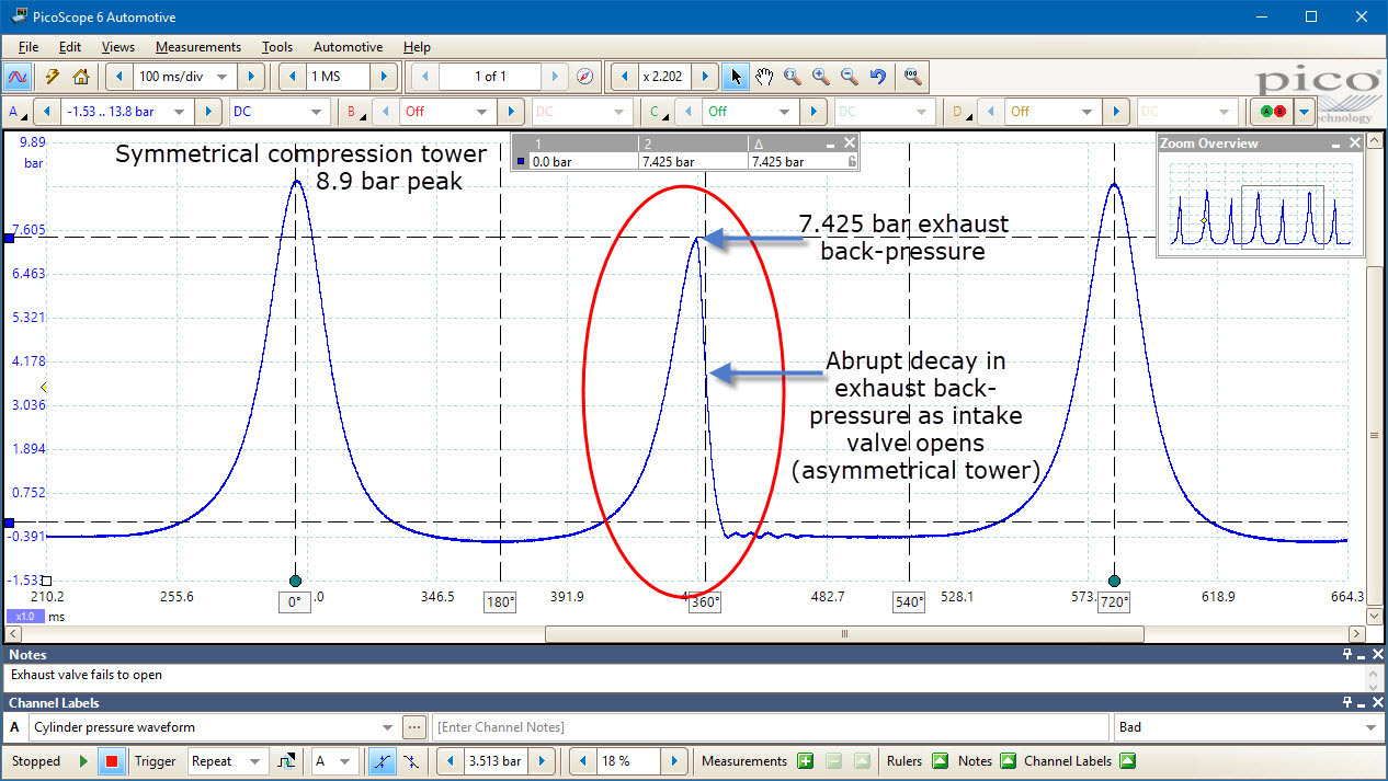
The Figure above reveals an additional pressure peak during the exhaust event that should not be present. As the piston rises from bottom dead center (BDC) of the expansion stroke (approximately 180 degrees after the TDC compression), the exhaust valve will open and release the cylinder pressure out to the atmosphere (atmospheric pressure) via the exhaust system. The waveform indicates a pressure increase to 7.425 bar during the exhaust stroke because the exhaust valve is not opening! In effect, we have another compression stroke during the four-stroke cycle – Compression-Expansion-Compression-Intake.
Air can be drawn into the cylinder and be compressed, hence the peak compression value (8.9 bar), but air cannot escape during the exhaust stroke.
Looking a little deeper at the exhaust stroke, we can see what looks like another compression tower/event being the result of the exhaust valve remaining closed. This time the tower is no longer symmetrical. Approximately 360 degrees into the crankshaft rotation, the intake valve opens abruptly, releasing 7.425 bar of cylinder pressure into the intake manifold. This is illustrated by a rapid drop in pressure and the asymmetrical tower. An event like this would manifest itself as a popping sound via the intake manifold.
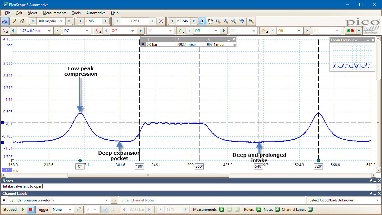
Figure 5 perfectly demonstrates the effect on peak compression as a result of the intake valve failing to open (447 mbar). While we have found a poor compression, we can also evaluate the cause looking at events during the four-stroke cycle between compression peaks. Looking at the expansion pocket, a near perfect vacuum is achieved at −992 mbar. At approximately 180 degrees into the crankshaft rotation, we can see that the exhaust valve has opened as the cylinder pressure returns from a vacuum at −992 mbar to 0 bar (atmospheric pressure).
Following on from 360 degrees of crankshaft rotation, a second and prolonged vacuum develops within the cylinder as the exhaust valve closes and the intake valve fails to open (the intake pocket). Once again an exceptional vacuum develops to form a deep and prolonged intake pocket, as a direct result of the piston descending the cylinder while the intake valve remains closed. The result of no air entering the cylinder is low peak cylinder pressure (compression), given there is no air present in the cylinder to compress.
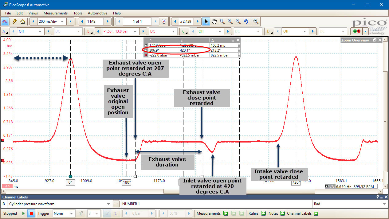
Figure 6 highlights the effectiveness of the pressure transducer when you are looking for valve timing and duration errors. This is thanks to the rapid response time to changes in pressure. Here we have an engine that fails to start, with a number of errors within the cylinder pressure waveform. By using the rotation rulers and partitions we can identify the precise point at which the exhaust valve opens. This proves to be retarded by approximately 44 degrees of crankshaft rotation Crank Angle (C.A). By placing the time ruler midway through the transition from the expansion pocket to near 0 bar (commencement of the exhaust stroke) the ruler legend indicates this event occurs at 224 degrees of C.A. Assuming that the exhaust valve opens at approximately 180 degrees (BDC expansion stroke) 224 – 180 = 44 degrees retarded.
Moving onto the intake valve, this is also retarded as the cylinder begins to pull a momentary vacuum at 424 C.A (instead of approximately 360 degrees C.A) until the intake valve opens and returns the cylinder pressure to 0 bar.
Note: the engine does not start, hence there is no intake pocket due to zero bar manifold pressure (o manifold vacuum). Additional items to note in Figure 7, is the low peak compression accompanied with a deep and enlarged expansion pocket. This is due to insufficient cylinder fill of air resulting in the retarded valve timing. The fault, in this case, was a worn crankshaft timing gear keyway, which resulted in the crankshaft timing gear rotating independently of the crankshaft.
Associated Links
Guided TestsDisclaimer
This training topic is subject to changes without notification. All rights reserved. The information within this file is carefully checked and considered to be factual. The information contained within these help files are examples of Pico Technology's investigations and findings and are not defined procedures. Pico Technology assumes no responsibility for inaccuracies.